


A compact, high-efficiency, fixed frequency, step-up DC-DC converter optimized as a light-emitting diode (LED) constant current generator can provide an easy-to-use power supply, with a small number of external components, for applications powered by one-cell and two-cell alkaline, NiCd and NiMH batteries. It could be integrated in various applications starting from the basic one-LED driver, powered from one-cell alkaline, NiMH or NiCd, to multiple infrared, white and RGB LEDs.
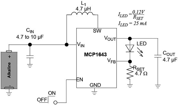
Figure 1: Typical application for step-up DC-DC converter
An example of this device is the MCP1643 from Microchip Technology. This is a pulse-width modulation-only device that operates at a fixed 1MHz switching frequency. Fig. 1 shows the device used as a simple DC-DC current source step-up boost converter that uses a resistor (RSET) to set the desired current.
The input voltage determines the maximum LED current. The device has an operating input voltage from 0.5 to 5V with 0.65V start-up voltage.
For a fully charged battery, the maximum regulated LED current is 450mA. Compared with alkaline, the NiMH and NiCd batteries have lower nominal voltage, so the maximum LED current delivered by the device will also be lower, around 350mA. The device will continue to deliver up to 150mA even when the batteries are almost depleted.
As with all LED current drivers, there are some limitations regarding the maximum and minimum load current limits.
The output LED current stays in regulation while VIN is less than VOUT with 300 to 400mV headroom because of the boost topology. The maximum load current is determined by the input current limit, which is 1.8A. If the selected LED current forces an input current bigger than the device’s maximum peak current, the LED current will be unable to regulate and will fluctuate with input voltage. The battery must also be able to sustain the amount of current needed by the converter.
The minimum output LED current the device can regulate is 20mA.
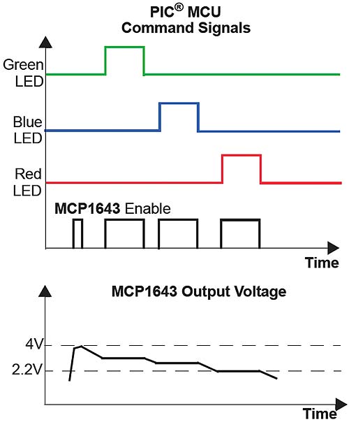
Figure 2: Theory of operation
One-cell LED driver
One of the simplest applications is as a constant current LED driver with a selectable current set by modifying the sense resistor’s value. For 2.4Ω, the set current is 50mA and can be increased to 100 and 150mA by connecting sense resistors in parallel. The device allows pulse-width modulation (PWM) dimming by turning the LED on or off with a variable duty cycle PWM signal applied to the EN pin. The maximum frequency for dimming is limited by the internal soft-start of typically 240μs. By varying the duty cycle of the PWM signal applied to the EN input, the LED’s average current is changing linearly and the light intensity changes as well.
Two series LEDs driver
The device can also be used to drive two LEDs in series. However, the maximum voltage is limited by the overvoltage protection that restricts the output voltage to 5.0V. Because of this protection, it can handle two low-voltage LEDs, such as infrared for remote control and red, but cannot handle high-voltage LEDs, such as white and blue.
Parallel LED driver
The device has a maximum output current of 550mA. To take advantage of this, low-current LEDs can be paralleled. The maximum number of LEDs is determined by the maximum output current of the converter (550mA) divided by the LED current rating.
For example, if the LED rated current is 50mA, up to 11 LEDs can be used. The same number of resistors is also required, with identical value. One pair, consisting of a LED and a resistor, is used to set the current measured by the device. The other pairs will follow, controlled by the first pair’s current.
This application is suitable for portable backlight devices where low-power SMD resistors are arranged in a line for LCD illumination. This low-cost, low-component count method replaces the need for a high-voltage constant current boost converter that may require a big inductor and occupy a lot of PCB space.
Embedded systems
An RGB LED is made of three LEDs (red, green and blue) with a common cathode or anode that can be driven simultaneously or one at a time to form any color of the visible spectrum. Each color of the LED has a different forward voltage, so a current source is needed to drive each LED independently.
The MCP1643 DC-DC converter can be used both as a current source for the high-power RGB LED and as a voltage source for a microcontroller. A one-cell AA battery can supply the power.
The device has a maximum output current of 550mA, but only one output. To drive three LEDs independently, it must be controlled by a microcontroller. Using a soft-start time of 240μs, the output can be multiplexed for each color without any current overshoot for an LED frequency of 70Hz. The LED current path has to be changed via external transistors to power each LED individually. In this application, the device can also be used for a brief period of time as a voltage source by disconnecting the LEDs and the feedback resistor and controlling the feedback voltage with a resistor divider to raise the output voltage to a fixed value of 4V.
Considering that the device is also used to drive three LEDs and power the control system, the chip will be enabled at a frequency of around 300Hz (approximately four times 70Hz).
To use the device as a multiple independent LED controller, some conditions must be met:
• The output must be moved from one LED to another with the same feedback resistor.
• The device must be disabled and re-enabled each time the control system changes the current path.
• The output voltage must be dropped to prevent any current overshoot when changing to a different LED color.
A PIC® microcontroller is required to accomplish this functionality. Figure 2 shows the timing of the control signals.
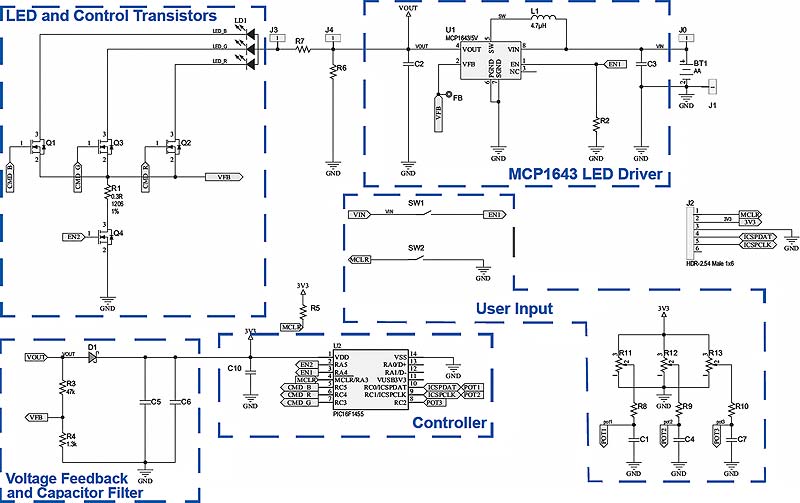
Figure 3: RGB LED driver demonstration board electrical schematic
The green, blue and red signals are the transistors’ gate voltages. These transistors are used to change the current path of each color. After they receive a command signal (gate voltage), the transistors will conduct and the corresponding color will form a closed current loop with the LED driver.
The enable signal is synchronised with these gate signals and has an additional enable period when no LED is controlled. During this period, the output voltage rises to a fixed voltage and the device acts like a voltage source.
Importance must be given to the order of the enable signals. Starting the device without connecting the LED to its output will cause the device to increase the output voltage to a maximum of 5V. If the LED is then connected into the circuit, the output capacitor will uncontrollably discharge into the LED, damaging the LED.
The dead time between the enable signals is different because of the forward LED voltage difference. For positive voltage transitions from low to high voltage, the dead time can be eliminated, but doing so is not recommended.
DC-DC voltage source
To use the device as a voltage source, a few external components are needed.
A transistor must be added to disconnect the feedback resistor from the feedback loop of the current driver, and a resistor divider in the feedback loop can raise the voltage to an appropriate level used by the control system. When the LEDs are not connected but the device is enabled, the output voltage increases to around 4V in a short period of time.
Because of multiplexing, the PIC microcontroller voltage is not regulated and will drop with time depending on the multiplexing frequency, the amount of stored energy and the power consumption of the control system.
If a more regulated voltage is needed, the device can be followed by an LDO. For example, if a 3.3V supply is necessary, a low-quiescent current low-dropout regulator (LDO), such as the MCP1702, can be used, and the output voltage of the MCP1643 should be set to more than 3.6V. The voltage drop will not influence the functionality of the microcontroller with a supply voltage of 2.3 to 5V.
Additional components are also needed to avoid interfering with the LED’s control voltages. A Schottky diode can prevent any voltage from going back into the LED and a capacitor can store the energy when the device is driving the LEDs.
Apart from not needing another DC-DC converter for the control system, this approach has another advantage. When the converter is turned off, the microcontroller will also be turned off. The entire system will only use the typical 1.2μA shutdown current of the device.
The system can be restarted either manually by enabling the device – which will automatically power the microcontroller as well – or by an external voltage source applied to the microcontroller for at least 100ms.
Figure 3 shows the electrical schematic of an RGB LED driver demonstration board. The schematic is divided into blocks that point to the functionality of each part of the system.
The PCB layout should be done with respect to the general DC-DC converter’s rules: the power traces that carry the most amount of current should be as short as possible and should not pass under or close to any sense or high-impedance signal traces. The switching node must also be as short as possible to decrease interference. The input and output capacitors should be as close to the converter as possible and the use of a ground plane is recommended.
For devices that tend to heat up, a lot of vias to a copper plane should be added to help with heat dissipation.
Conclusion
The MCP1643 is a versatile synchronous boost DC-DC LED driver converter designed for one-cell alkaline battery-powered applications with low start-up voltage and high current capabilities. The low standby (shutdown) current of 1.2μA increases battery life when not in use, while the low component count and low PCB area occupied allow for use with smaller, more portable applications.
Designing DC-DC converters with the device is straightforward and, by attaching a microcontroller, the designs become more versatile and user-friendly.
Microchip Technology
www.microchip.com