


From the smallest to the largest, all electronic equipment requires power supplies, and with the increase in the amount of wireless connected devices deployed in the medical environment, electromagnetic compatibility (EMC) has become a big concern for all users. In the vast majority of applications the power supplies’ EMC is manageable, but in some extremely demanding areas such as Magnetic Resonance Imaging (MRI), the challenges for power supplies manufacturers are twofold, not to disturb the sensitive equipment, but also not to be disturbed by the multi tesla (T) magnetic field generated by the core of the MRI.
How to guarantee that power supplies exposed to such extreme conditions will do the job?
From Conrad Roentgen to Raymond Damadian
As long ago as 1895 Conrad Roentgen found that an emitting discharge tube contained in a sealed box and radiating in the direction of a paper plate covered on one side with barium platinocyanide became fluorescent, and even when an object was placed between the tube and the plate a picture was obtained; the first X-ray. Fast forward to to 1977 and Raymond Damadian was performing equally groundbreaking experiments with his Nuclear Magnetic Resonance (N.M.R.) body scanner to produce much more detailed images of the inside of a human body. In both cases the images obtained have contributed greatly to improve medical diagnostics, the quality of treatment and peoples’ lives.
From the original X-Ray equipment and the Damadian NMR to the latest MRI technology offering extremely high resolution imagery, all share a common need for a large variety of power supplies delivering from a few watts to multiple kilowatts. As the level of imaging resolution has improved, MRI manufacturers are designing new equipment placed very close to intense magnetic fields requiring very stable power that does not interfere with the data acquisition process.
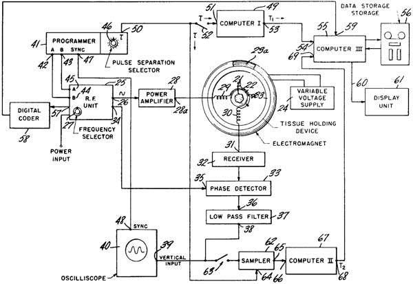
Figure 1: 1974 Damadian patent
Operating a switching power supply in very high magnetic field environments is very challenging and even reaches certain technical and physical limits as we know them today. To surpass these limits, power designers are exploring new paths, combining state of the art power conversion topologies with advanced software and digital technologies. This is a very interesting area for power designers to explore but before revealing the magic power solution, let us understand how MRI works and what are the challenges power designers are facing in such extreme environments.
From discovery to practice
X-Ray equipment has contributed to impressive medical progress but the resultant images are limited to identifying solids, and exposure to radiation is dangerous for patients and operators. These drawbacks provided the original motivation for the physician and scientist Dr. Raymond Damadian to explore a new new way to scan the human body by researching the properties and behavior of an atomic nuclei when exposed to a magnetic field. After more than 10 years of research and a mix of successes and failure, in March 1972 he applied for a patent for an “Apparatus and method for detecting cancer in tissue” which USPTO granted in February 1974 (US3789832) (Figure 1).
“An apparatus and method in which a tissue sample is positioned in a nuclear induction apparatus whereby selected nuclei are energized from their equilibrium states to higher energy states through nuclear magnetic resonance. By measuring the spin-lattice relaxation time and the spin-spin relaxation time as the energized nuclei return to their equilibrium states, and then comparing these relaxation times with their respective values for known normal and malignant tissue, an indication of the presence and degree of malignancy of cancerous tissue can be obtained.”
When Nikola Tesla revealed the evidence of the rotating magnetic field in 1882, he could hardly have imagined that 90 years later it would lead to Dr. Raymond Damadian using a magnetic field to see inside bodies! And for sure, no-one could have imagined the level of resolution that modern MRIs have achieved.
Let’s see at a glance how MRI works and how power supply designers have invented new power solutions able to operate in multi tesla environments.
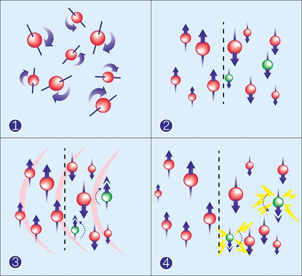
Figure 2: Hydrogen nuclei polarization during the MRI activation phases
Hydrogen nuclei are the key in MRI!
As we learnt at school, the human body is composed of 70% water. Water molecules are made up of two hydrogen atoms and one oxygen atom (H2O). An MRI machine can identify hydrogen nuclei contained in water molecules, which have a quantum physics property called spin. We can assimilate the Hydrogen proton to the planet earth rotating on its axis, with a north and a south pole. Under normal circumstances, these hydrogen proton bar-magnets spin in the body with their axes randomly aligned (Figure 2.1).
When the patient’s body is placed in a strong magnetic field the protons’ axes all line up. This uniform alignment creates a magnetic vector oriented along the axis of the scanner (Figure 2.2). Depending on the object under observation, the MRI scanners have different field strengths, usually between 0.5 and 3 tesla (T) (note that the gauss unit is often used as well: 1 tesla = 10.000 gauss). The latest generation of MRI reach six tesla, thus Neurospin brain research is using 11.7 T, which is 234.000 times the Earth’s field, and in the case of spectroscopy even up to 20 T. The main magnetic field is referenced as vertical or B0 (B zero).
When additional energy in the form of a radio wave is added to the magnetic field (B0), the magnetic vector is deflected. The radio wave frequency that causes the hydrogen nuclei to resonate is dependent on the element sought and the strength of the magnetic field (Figure 2.3). Two magnetics fields are used, the Gradient (B1) and the RF field.
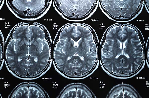
Figure 3: Brain high resolution picture obtain after data acquisition
When the radio frequency source is switched off, the magnetic vector returns to its resting state, and this causes a signal (also a radio wave) to be emitted. It is this signal which is used to create the MR images. Receiver coils are used around the body part in question to act as aerials to improve the detection of the emitted signal (Figure 2.4).
The intensity of the received signal is then plotted on a grey scale and cross sectional images are built up (Figure 3).
Multiple transmitted radio frequency pulses can be used in sequence to emphasize particular tissues or abnormalities. A different emphasis occurs because different tissues relax at different rates when the transmitted radio frequency pulse is switched off.
This simple description highlights the level of the strong magnetic fields involved in the hostile environment of MRI applications, in which power supplies designers must take into consideration when developing products for such types of demanding applications.
Forces in power
To understand what power designers have to consider, it is important to understand the magnetic and electromagnetic forces involved with an MRI scanner and how they can interact with the power supply, which can also interact with the sensitive data collected by the different sensors.
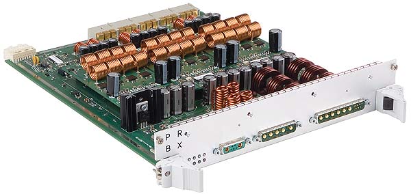
Figure 4a: Triple outputs, multi-phases, PRBX coreless power supply sustaining B0 field
Master magnetic field (B0)
B0 is generated by a permanent or superconducting magnet and is oriented along the main axis of the scanner (Z axis). Depending on the application, field intensity varies from 0.5 T up to 20 T.
Gradient fields (B1)
B1 is generated by a specific combination of coils in the three axis X, Y and Z. The pulsed frequencies are around 100 KHz with intensity as low as few mT/m. The frequency is adjusted to suit the object being examined and the frequency can be modulated.
RF field
The RF field is generated by a separate coil in the X and Y-axis. The frequency range is comprised between 64 MHz and 299 MHz with micro-tesla intensities.
How to provide power in such environments?
To avoid interference the best practice in powering MRI is to avoid alternative voltage/current (AC) and to only use continuous voltage/current (DC), even for lighting. Master power supplies are traditionally positioned outside the shielded operation room and the DC voltage distributed to the electronic equipment via shielded cables.
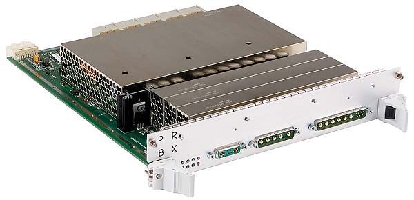
Figure 4b: PRBX coreless power supply sustaining B0 field shielded to protect against interferences
To adjust the voltage from the main DC line to a specific load (e.g. 24 VDC to 12 VDC), the old generation of MRI equipment used a large variety of linear step-down voltage regulators, which reduces the risk of disturbances but inherent to their technology have a very low energy efficiency and high power dissipation. Requiring more power and better energy utilization, new generations of equipment have adopted switching power regulators, which paradoxically have improved power efficiency but have also became a source of potential disturbances! When the power supply is far enough from B0 and sensitive equipment, efficient shielding and grounding can prevent interference but when the power supply is located close or even within B0, then power designers are facing real challenges.
MRI impact on the power supply
Master magnetic field (B0)
A switching power supply transforms a DC voltage into an AC one, and then rectifies it to DC. During the conversion process the transferred energy is stored in a transformer composed of a coil(s) and a core, usually made of ferrite. The high density of B0 interacts directly with all ferromagnetic components, saturating iron-cores and making it impossible to transfer the energy and even becoming a short circuit.
Gradient fields (B1)
The gradient field frequency is very much the same as the average switching frequency of conventional power supplies but induces a ‘current storm effect’ in cables and conductive areas. This also affects the switching performance of the power stage resulting in signal distortion, heat and in most of the case short circuit of the switching components.
RF field
Due to its much higher frequency, the RF field is less harmful for the power supply though induced currents could result in the form of similar collateral defects as generated by the B1 field.
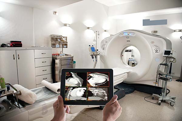
Figure 5: MRI equipment with advanced data acquisition requires very stable power supplies able to operate in high magnetic field — Source: iStock / baranozdemir / PRBX
Power supply impact on MRI
Master magnetic field (B0)
Even though the Larmor frequency is 42.58 MHz/Tesla for protons (hydrogen nuclei), there is a risk that the power supply switching spikes can impact the signal with the consequence of generating artifacts that affect image quality and resolution.
Gradient fields (B1)
Because the switching frequency of a standard power supply is in the same range (100 KHz) of the gradient filed, that could interfere with the signal generated by the gradient loop, and as a consequence modify the encoded signal, resulting in image artifacts.
RF field
In the case of RF, the harmonics of the fundamental switching power supply could interfere with the RF coil loop causing alteration of the MRI RF signal and a negative effect on image quality.
How then, to make a power supply that works?
Taking into consideration the different parameters, it is obvious that a suitable power solution will have to exclude ferromagnetic components and its switching frequency must not interfere with the MRI signals.
Because conventional magnetic cores will saturate when exposed to the B0 field energy, air-core inductors, having no ferromagnetic core material, should be considered. One downside of air-cored inductors is their low inductance values, which can be compensated by designing a multi air-cored power stage operating in parallel. Controlling multi-parallel air-cored power supplies requires the implementation of the latest digital control technology, offering a high degree of flexibility in how the different power channel operate. Digital control allows designers to adapt the profile of the power supply to specific conditions.
In Figure 4a is an example of an advanced air-core power supply, the PRBX GB350. To accommodate the specific MRI, B0, B1 and RF specifications that it has been designed for, the GB350 has a fundamental switching frequency of 600kHz. With such a switching frequency and its four phase interleave mode, the GB350 has a resultant output frequency of 2.4MHz. This allows easier filtering and extremely fast regulation response times. The unit also includes EMI shielding to lower radiated emission and prevent any risk of artifacts (Figure 4b).
In conclusion
In less than 50 years, the progress of the Magnetic Resonance Imaging (MRI) scanner has been really impressive and image resolution quality, astonishing (Figure 5). By permanently innovating, the power supply industry has contributed to delivering efficient, sustainable and safe power to very demanding applications such as B0 field conditions. Ultra-high field strength systems with a new generation of sensors will require extremely fast response power sources switching at 25 MHz to avoid harmonics in the safety band and I can foresee a new generation of coreless power supplies combining air-core, digital control and the use of Gallium Nitride (GaN) transistors.
There is no doubt, power designers developing power solutions for medical imagery systems will continue to make magic a reality!

Author: Patrick Le Fèvre, Chief Marketing and Communications Officer
Powerbox – A Cosel Group Company| www.prbx.com
![]()