


The project took place during the summer school, in collaboration between Microchip Technology and InGeAr laboratory from Polytechnic University of Bucharest. We would like to thank to our mentors from the Microchip team, especially to Mr. Horia Boicu, for his patience and guidance which he showed.
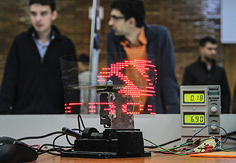
This article presents a complex application – a display system based on optic effect called “persistence of vision” – in which implementation we passed through a spectacular learning process. Now, we’ll like to share some aspects of this experience with you.
Authors:
Vladimir Oltean – olteanv@gmail.com
Iulian Calciu – iuliancalciu@gmail.com
Alexandra Marinescu – alexa.alyas@yahoo.com
Alexandra Ştefănescu – s.alexandra.stefanescu@gmail.com
Operating principle and general presentation
Persistence of vision (PoV for short) is the optical illusion of continuous motion that occurs on the retina when still images are viewed in rapid succession. This is due to the chemical transmission of nerve signals, this biochemical hysteresis being much slower than the speed of light.
In order to better understand the phenomenon of vision persistence we have to remember that the eye does not work like a camera, in the sense that vision is not simply light striking a sensor. The brain must process he visual data transmitted by the eye and construct a coherent image of reality. Thus, the eye does not have a “frame rate”, instead the whole eye-brain system functions like a collection of sensors that detect motion, details, and models, and the data recorded by these sensors are combined to create a visual experience.
Since the 19th century, there have been optical devices that could generate persistence of vision. Some of those are: the thaumatrope – a disc containing several images and spins rapidly; the stroboscope and praxinoscope – on a piece of paper on the inside of the cylinder are drawn sequences representing motion. Today, most cartoons or animations are created based on this mechanism.
Wishing to learn more about this remarkable phenomenon, not only on a theoretical level, but also on a practical one, we decided to build such a device.
Supported by the InGear lab, a center where students that are passionate about hardware, electronics and robotics have the opportunity to work on these types of projects, and also by Microchip Technology, we succeeded in assembling our own PoV device. Videos with the device in operation can be found on the “eap.ingear” Facebook page.
Layout and mechanical design
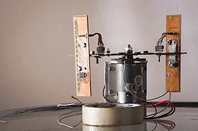
The device consists of a main rectangular board, centered on the vertical shaft of a motor, and which rotates along with it. On its sides, attached to the far ends with 2 metallic L-shaped braces, there are 2 other boards, perpendicular to the main board. Together, these form a T-shaped assembly.
The side boards each have 16 LEDs, interspaced alternatively on the vertical axis. Thus, the vertical resolution is 32 “pixels”, with the even lines displayed on one board, and the odd ones displayed on the other. The horizontal resolution, on the other hand, is adjustable, the image in the memory being “stretched” to fill up 360 degrees.
The greatest mechanical difficulty encountered was that of centering the main board, which is why we chose not to use a battery (see Electronic Design). For centering, we used the following method: set the main board on a horizontal rod, nudge it and wait for it to stop. If it oscillates it means it is not centered. A centered board correctly should stabilize without oscillations in any position, and not with the heavier side pointing downward. For centering we used both the repositioning of various components, and adding solder to the ground plane of the lighter side.
Electronic design
The POV uses 2 separate power sources: a high load one (for the motor), and one for the logic circuits.
Although the initial plan was that the engine voltage would be controlled by PWN with a PID algorithm, on the way we found this unnecessary, with all its entailed complexities. Thus, currently the DC motor uses 2 adjustable voltage sources connected in parallel.
As for the power source for the logic circuits, the initial plan was also different, namely to mount a battery on the main board, as close as possible to the center. Due to the stability problems mentioned above, we opted to transmit the energy via brushes (details follow). We do not refer here to a brushed DC motor, but to 2 actual brushes that come into contact by friction with 2 circular rings on the main board, centered in the hole for the motor shaft.
The “brushes” are in fact metal springs, electrically isolated from the engine’s power, but mechanical fixed on its casing, which we connect to a power source.
The fact that the brushes are in contact with the tracks on the board allows power to be transmitted without the need for a battery. In practice, the contact between the brushes and the board is far from perfect, which results in very high noise on the power line. In consequence, the controller resets, i.e. the Zener diode and the voltage comparator inside it detect that the voltage has dropped below the critical threshold for correct operation (the frequency of operation of a CMOS circuit is proportional to the supply voltage!), and resets. One way to counteract the damages done by these variations is using capacitors to filter out the brush noise.
The effective value of the logic supply voltage is around 8 – 8.5V, and it is routed through 2 linear stabilizers: a LM7805 and an NCP1117DT33G, that bring the voltage down to 5V and 3.3V, respectively.
The only component that uses 3.3V is the Bluetooth module (the RN42 chip), while all others are connected to 5V (this allows the controller to run at a higher frequency).
The side boards are connected to the main board via a ribbon cable with 6 lines: VCC, GND,
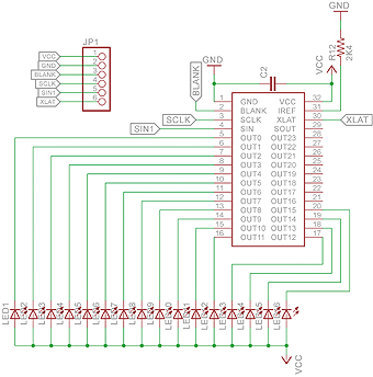
SIN, SCLK, BLANK and XLAT. More details about the serial transmission will be given in the chapter on programming, but it is sufficient to say that these wires are required by the LED driver, a TLC5947 from Texas Instruments. This is built effectively like a shift register with 288 bits, grouped in 24 sets of 12. Thus, it can control up to 24 LEDs in parallel, and each 12 bit set represents a PWM value from 0 and 4095, with which it is possible to individually adjust the intensity of the LEDs.
The driver must power the LEDs from a fixed current power supply, implemented as a current mirror for the reference current that can be set on the Iref pin, by adjusting the Rref resistance (2.4 kOhm results in a 20 mA current).
In order to detect a 360 degree revolution, we use a Hall sensor that reacts to the magnetic field of the 2 sensors placed on the fixed rod near the motor. In principle, the sensor gives off a voltage of approximately 0.45V when activated by the north pole of a magnet, and 0V when activated by the south pole. Because the output voltage exhibits reminiscence, even after the magnetic field is removed, a second magnet is necessary to ensure a low to high transition. In order to aid the sensor, we also used an operational amplifier, LM324, in order to bring the “high” output voltage to a logically acceptable level. The reaction loop of the op-amp is adjustable with a small potentiometer.
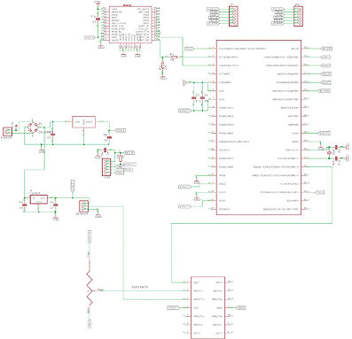
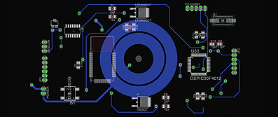
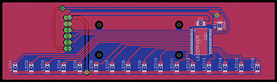
The electrical diagram was drawn in Eagle, and was designed as a two-sided PCB, with 1 mm thick power lines, and 0.4 mm thick logical ones. The packages used were SMDs for all the components used (aside from the electrolytic capacitors used in filtering the power transmitted via the brushes).
The communication between the microcontroller and the Bluetooth module is a worthy subject to present, both by its electronic nature and programming.
Logically, they are connected by a UART (Universal Asynchronous Receiver/ Transmitter) interface, a protocol based on the RS232 serial standard, but adapted to lower logical levels (the standard specifies between -3 and -12V for “1” and between +3 and +12V for a “0”). Due to this fact, we will only use the Rx, Tx and GND lines, for a full-duplex communication between the Bluetooth module and the microcontroller.
From an electrical standpoint, it is necessary to connect a 5V device with a 3.3V one: from the controller side we used a resistive voltage divider, and in the other direction we relied on the 2.5V threshold voltage and the good noise margin of the CMOS chip, connecting the RN42 output to the microcontroller’s input.
Programming
And since we are on the subject of the microcontroller, for the heart of the project we used the dsPIC30F4011 controller from Microchip, a 16bit DSP that can run at up to 120MHz.
It was programmed using the MPLAB X IDE, also from Microchip, using the C programming language. There were a few tries to introduce assembly language code, but those particular bits were replaced, since their speed of execution was not critical. The compiler used was the free version XC16, without optimizations.
The microcontroller clocking is set by default by an internal RC oscillator that runs at 8 MHz (comparable to Intel 80286 in 1982!). Due to the fact that this speed is insufficient (the pixels to appear as horizontal lines) we decided to use an external 6 MHz quartz oscillator.
Then, using the embedded PLL (Phase-Locked Loop) circuit, we multiplied this frequency 16 times, thereby obtaining an effective frequency of 96MHz.
The timing of the instructions in the PIC family, as with the majority, of RISC architectures, is a very simple one: one instruction cycle is completed every 4 clock cycles. We thus obtain:
Fpri = 6 MHz, PLL = 16x
Fosc = Fpri * PLL
Fcy = Fosc / 4
Knowing the fact that this processor’s pipeline is also a very simple one, with 2 stages, we reach the conclusion that it runs at 24 MIPS, which is to say, it starts a new instruction every 41.6 nanoseconds.

That being said, the program relies on the following algorithm: it installs a Change Notification interrupt on the pin that is linked to the Hall sensor, then it measures the time interval between 2 consecutive activations. This interval represent the duration of one complete 360 degrees revolution. If we want to display all the columns of the image within this time, it means that each column must be displayed for an interval equal to the duration divided by the number of columns.
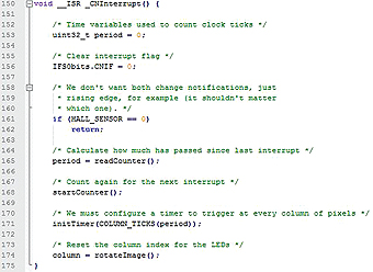
The timing of this new display is done by another interrupt, installed for Timer 1. In order to time the interrupts of the Hall sensor, we use a 32 bit timer (Timer 2/3 concatenated), in order to raise the precision of the measured interval to a theoretical value of 232 * 41 ns, approximately 176 seconds, at the same time keeping the 41 ns resolution, with a 1:1 prescaler.
We can now flesh out the serial data transmission needed to display a new column. The method used is called “bit banging” and has a particularly low complexity. Basically, it implies connection the SIN/SOUT and SCLK transmission pins (serial in/out and serial clock, lines that define the I2C interface), directly to the general-purpose ports of the microcontroller. In this way they can be set directly, via instructions such as SOUT = 1; SCLK = 1; SCLK = 0; without having a very good control over the clock fill factor that results from alternating the SCLK line. If this control were strictly necessary, it would have been necessary that the number of instructions executed by the processor after SCLK = 1; be equal to the number executed after SCLK = 0; and this aspect is very difficult, if not impossible to control, as long as programming is done in C, and not in assembly language (we cannot be certain of the machine code generated by our compiler).
The LED driver works as follows: at each rising edge on the SCLK line, the data in the shift register is moved one position to the right, in order to make room for the new bit (read on the SIN line) in the MSB (Most Significant Bit) position.
Transmission stops at the rising edge of the XLAT (latch data) line, through which the bits are copied from the shift register in the LED control latches.

These are turned-on on the low level of the BLANK line, and stay on until the next falling edge. The GND line ensures that the main and lateral boards have the same ground potential, and prevents the formation of ground loops.
One final aspect that remains to be discussed is storing the images in memory. A short look over the architecture of this processor indicates a Harvard CPU, with different memory spaces for code and data. More precisely, the instruction memory is mapped over a 144KB EEPROM memory and the data area over a 4KB flash memory, which is by far insufficient to store an image with a 12 bit color depth, which is what the LED driver is capable of. For this reason, we opted for a much more compressed representation of the image, splitting it in 2 matrices and represented by column, each one a 16 bit number (1 bit = 1 pixel).
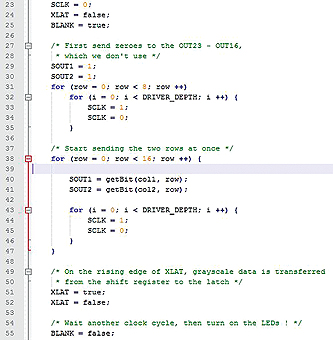
Transmission is done simultaneously for both lateral boards, and at any point in time, the second boards displays the column 180 degrees opposite to the first board (they are always 180 degrees apart).
Once the proper bit is set on the SOUT line, the clock (SCLK) is toggled 12 times, in order to produce the number “000…0” or “111..1”, that is 0 or 4095 (minimum or maximum). We have this reduced the color depth from 12 bits to 1 bit.
Even so, the 4KB memory is insufficient to store more than one image at a time. The current method of changing the image is by reprogramming with a new hardcoded matrix, but an application for the Bluetooth mode is in development.
Image generation is done on a computer, in a preferred text editor (the images were created with Vim), using something not entirely different from ASCII art, they are then converted by a small program into code that can be inserted directly in the POV program.
Plans and future modifications
At the present time, the brush springs have a suboptimal contact to the board, which leads to unwelcome resets of the microcontroller. These will be replaces with new, coal brushes that give better results under wear and protect the copper rings on the central board.
An application to communicate with the POV in order to transmit images via Bluetooth will be ready at the same time with the mechanical upgrades. The vice holding the assembly right now will also be replaced with move adequate supports.