


 Wearable technology has never been in the news as much as it is today. The march of the wearables – a generic term for electronic devices worn on the body that monitor how the body is functioning – looks unstoppable.
Leading this trend are activity trackers, measuring the numbers of steps taken, encouraging the wearers to engage in proper daily exercise that can reduce blood pressure and body mass index. Bracelet-type activity trackers combining step counters and Bluetooth Low Energy are becoming popular as motivation tools for those wanting to improve their physical activity and health.
A digital pedometer is a portable electronic device that counts each step a person takes by detecting the motion of the person’s body with an accelerometer. Such a device can be built using an 8bit microcontroller, a Bluetooth Low Energy module and a digital triaxial accelerometer. This demonstration device can be worn on the wrist as with a bracelet or watch. The on-board Bluetooth LE module allows the pedometer to communicate with a smartphone or tablet on which the user’s exercise progress can be tracked.
Figure 1 shows the block diagram of such a pedometer using a Microchip PIC16LF1718 microcontroller, Microchip RN4020 Bluetooth LE 4.1 module, Bosch Sensortec BMA250E digital triaxial accelerometer and CR2032 3V coin lithium battery.
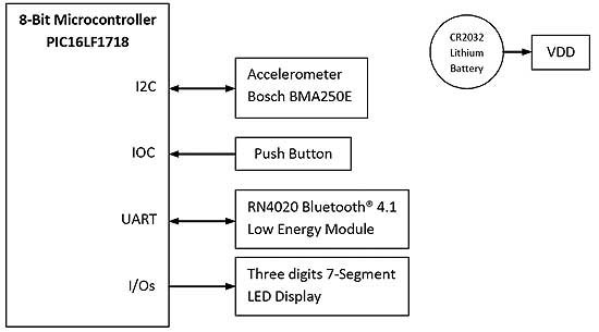
Block diagram of pedometer demo
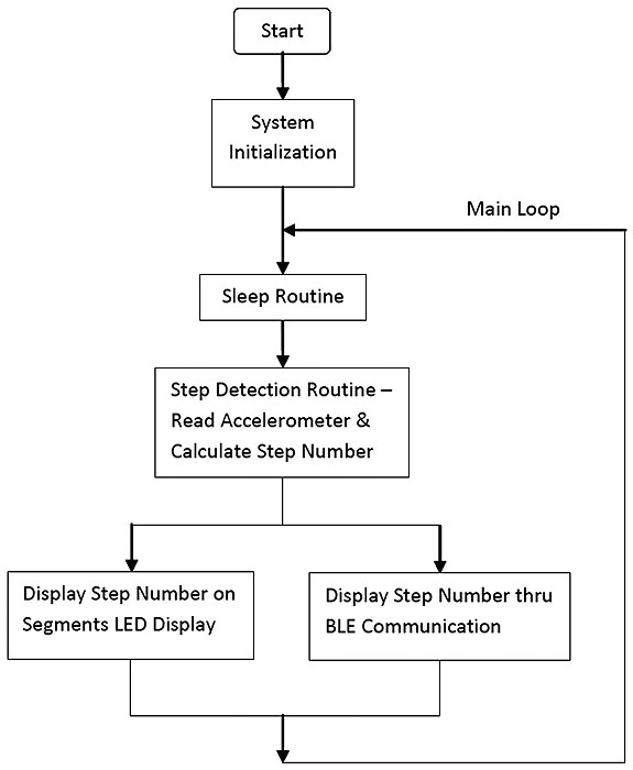
Firmware process flow of the pedometer demo
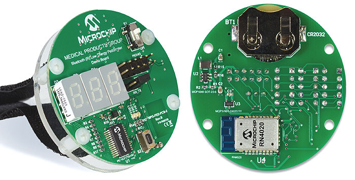
Front and back of the pedometer demo board
Operation
The 10bit accelerometer detects the motion of the wearer. Firmware in the microcontroller contains a step-detection algorithm developed by Bosch Sensortec. A step-detection function in this library is called periodically by the user application.
The microcontroller reads the acceleration data along the x, y and z axes from the accelerometer via an I2C interface when the step-detection function is called. The step-detection function then analyses the accumulated acceleration data and uses pattern recognition to determine the number of steps taken.
The accumulated number of steps can be shown on a three-digit seven-segment LED display or, via Bluetooth LE, on an application running on a smartphone or tablet. Figure 2 is a flowchart that show the process flow of the pedometer demo. The Bluetooth LE module with which it is paired complies with the Bluetooth 4.1 core specification and supports 13 public profiles and 17 public services based on the GATT general attribute profile. Among the supported public profiles, four are health based – heart rate monitor, health thermometer, glucose meter and blood pressure monitor.
The module also supports a user-defined private profile or service that can precisely fit the user’s application. In this case, the demo defined a private service for the pedometer application.
All configurations are saved in the on-board non-volatile memory of the Bluetooth LE module so that users need to set up the module only once. The microcontroller activates the module when the Bluetooth LE communications are enabled by pressing the on-board button. The module then becomes pairable with a smartphone or tablet. The microcontroller periodically sends the step number to the module via a UART interface after successful pairing. The module then transmits the step number to the paired mobile device, where a compatible Bluetooth LE application can be used to display the step number.
However, a companion application may not be needed if the device has Apple HealthKit installed, a feature for iOS 8 and later that adheres to the Bluetooth LE GATT specifications. This means that medical devices such as heart rate and blood pressure monitors, thermometers, and glucose meters that are built with the RN4020 module will be supported natively by Apple HealthKit. So instead of developing a companion application, device manufacturers can allow Apple HealthKit to control the device or accessory automatically when it is paired with the Bluetooth LE module.
One button provides quick function control to the pedometer demo via the interrupt-on-change (IOC) interface. To turn the LED display on or off, the user needs to press the button and quickly release it within one second. To enable or disable Bluetooth LE communications, the user needs to press the button down and hold it for more than one second but less that four seconds. Holding the button down for more than four seconds and then releasing it will zero the step number.
Power
Power for the pedometer demo comes from a single 3V lithium coin battery. The LED displays are automatically turned off after ten seconds to save power. The baud rate of the UART communications is set to 2400kbit/s so that the Bluetooth LE module can remain in deep sleep mode when there are no UART data communications. If there is no motion for 16s, the accelerometer will send a no-motion interrupt to the microcontroller via the IOC interface. When the no-motion interrupt occurs, the microcontroller reconfigures the accelerometer to high-g interrupt and puts it into a low power mode, after which the microcontroller itself goes into sleep mode so the overall system is consuming the lowest possible power.
During the low power mode, the accelerometer is periodically switching between a sleep phase and a wake-up phase. While in the sleep phase, the whole analogue circuit of the accelerometer is powered down. In wake-up phase, the accelerometer works normally and the high-g interrupt function is running to determine when to wake up from the low power mode.
The accelerometer generates a high-g interrupt to wake up the microcontroller when the wearer’s motion is over the pre-set threshold for a high acceleration event, such as walking, picking up the pedometer, or waving or rotating the pedometer in the air. The pedometer resumes normal operation after waking up.
Conclusion
This article has shown how to build a pedometer than can communicate via Bluetooth LE for evaluation and development purposes. It is not intended for medical, diagnostic or treatment use, but can be a useful device for people keen to monitor and increase the amount they exercise.
Zhang Feng is an engineer at Microchip Technology.
Microchip Technology | www.microchip.com
![]()