


High-bandwidth In-Vehicle Infotainment (IVI) systems with data rates higher than 100 Mbit/s have been historically offered in high-end cars; however, more and more economical and high-volume passenger vehicles are also beginning to offer high-bandwidth IVI capabilities. Independently from the software-based features that different IVI systems can offer, all of them share a common base: the need for robust and high-bandwidth underlying physical-layer technology.
Historically, optical MOST150 networks have served the purpose of being the high-bandwidth infotainment physical layer, fulfilling all of the demanding OEM requirements with respect to the high bandwidth, scalability, low weight, high robustness, EMC and the capability to fit in to the limited available space in vehicles. However, in spite of the listed features, its cost has represented a barrier for some high-volume car manufacturers.
The need to answer the market demand for a cost-down path for the IVI physical layer, capable of fulfilling the challenging automotive requirements, has triggered an innovation process that has generated a new standardized physical layer for IVI networks based on coaxial cables.
Coaxial cables have many design merits, including:
• Supporting high-bandwidth data transfer
• High shielding effectiveness – robust EMC performance
• An available automated connectors assembly process
• Satisfying demanding mechanical requirements such as bending capability and high temperature range
• Cost effective for an automotive-grade solution
• Tightly controlled impedance, enabling full-duplex mode of operation
• Making power transmission along with data possible over the same cable
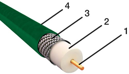
Figure 1: Cutting Model of a coaxial cable 1 = center core conductor 2 = inner dielectric insulator 3 = metallic shield 4 = plastic jacket
Furthermore, they have already been used in the automotive industry for decades with a proven track record as point to point connections cables. Examples of this include being used for connections between antenna and radio or connections between antenna and a Global System for Mobile communication (GSM) module; therefore, the existing infrastructure for highly-automated production and the corresponding supply chain is well established. Consequently, automotive requirements regarding temperature range and mechanical requirements are fulfilled as well. Additionally, a standard for automotive connector models (FAKRA) is also available and has been adopted by different suppliers. FAKRA connectors exist in many different shapes and are provided with different color and mechanical coding schemes allowing an easy and time-optimized assembling process at the vehicle production line. FAKRA connectors fulfill the demanding automotive requirements as well and can be produced using methods with high grade of automation.
Figure 1 illustrates the cross section of a coaxial cable. This model shows at a glance the biggest advantage of a coaxial cable, as the electric field associated to the signal transmitted through the core conductor (1) is contained within the space limited by the metallic shield (3). The consequence of this is that the coaxial cable does not radiate energy externally. At the same time the shield (3) protects the core conductor (1) from external electric fields providing high signal immunity. These two properties of coaxial cables are responsible for the robust electromagnetic compatibility (EMC) performance that facilitates the positioning of a coaxial cable in a vehicle. This also represents a cost saving factor because there is no need to develop special cable routing or observe strict limitations for positioning coaxial cables.
Coaxial cables offer features that are not available in a classic optical MOST® system.
One of these advantages is based on the controlled impedance of coaxial cables that makes it possible to have both a Dual Simplex (DS) communication and a bidirectional Full Duplex (FD) communication as well. This allows the implementation of additional network topologies in comparison to the classic MOST ring and represents an important innovation in IVI networks. For special use cases a combination of DS communication and FD communication could also be implemented. Table 1 summarizes possible topologies that can be implemented using a coaxial physical layer. Let us see in detail all the networks topologies that can be implemented using a coaxial physical layer.
| Communication | Topology |
| Dual Simplex | Ring |
| Full Duplex | Point to Point connection |
| Full Duplex | Daisy Chain |
| Full Duplex | Star |
| Dual Simplex and Full Duplex | Hybrid |
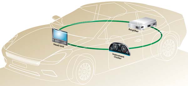
Figure 2: Infotainment system consisting of three nodes connected in a ring topology based on Dual Simplex coaxial physical layer.
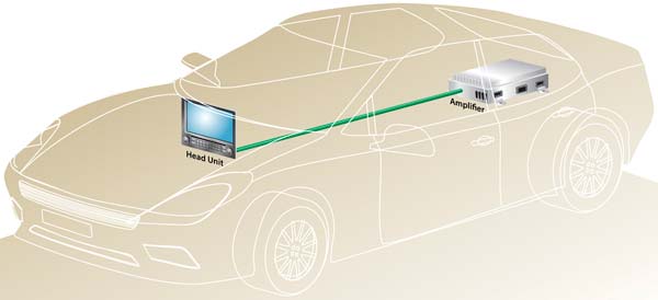
Figure 3: Infotainment System consisting of two nodes connected in a point to point connection based on a Full Duplex coaxial physical layer.
Table 1: Summary of possible network topologies on a coaxial physical layer for IVI systems
The classic MOST ring on a coaxial physical layer can be implemented as it is shown in Figure 2. This kind of network topology is based on a unidirectional DS communication that requires a return cable that closes the ring structure. Using the FD communication instead allows designers to implement topologies that are otherwise not possible. For example, considering a two node system, a pure point to point connection as shown in Figure 3 can be realized. In this case, thanks to the bidirectional communication of the FD coaxial line, there is no need to put in place a return cable. The biggest advantage of this topology is a system cost saving of up to 50% in comparison with a classic optical two nodes MOST ring is achieved. This cost saving option is very interesting for high-volume car manufactures because with a two node system a basic but powerful infotainment system, consisting of a head unit and an amplifier, can be implemented.
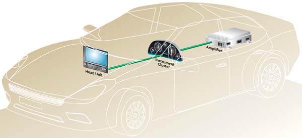
Figure 4: Infotainment system consisting of three nodes connected in a daisy chain based on a Full Duplex coaxial physical layer.
For more complex architectures with three or more nodes, the FD communication allows designers to implement a daisy chain topology between the IVI nodes. An example of a three node infotainment system in a daisy chain topology is shown in Figure 4. Also in this case, the absence of a return cable simplifies the car assembly process and contributes overall system cost reduction.
Another network topology that is possible with three or more nodes on a coaxial physical layer using FD communication is the hub configuration. An application example is shown in Figure 5. An in-car display unit acting as a hub is connected point-to-point with two rear view cameras that substitutes external mirrors.
The combination of DS and FD communication allows designers to add new applications to an existing infotainment system based on the ring topology. An example could be to add an audio subdomain with a microphone network to an existing system that was originally developed without supporting a microphone network.
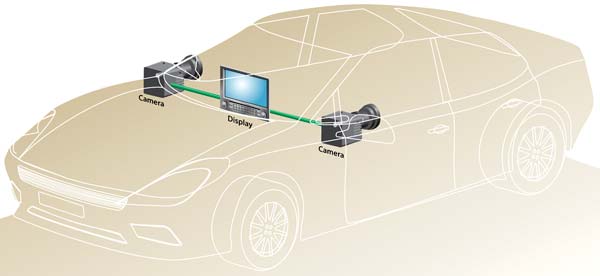
Figure 5: Example of hub configuration based on coaxial physical layer.
All shown topologies optionally support the transmission of power over the coaxial data line. This allows designers to save dedicated power lines and connectors for each node in the network that is powered over the coaxial cable. This permits cost and weight savings, as well as an easier car assembly process.
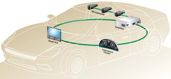
Figure 6: Example of how an existing Infotainment System based on a coaxial physical layer ring can be expanded with the Addition of a daisy chain.
Architectures shown in Figure 5 and Figure 6 are perfect examples for illustrating the advantages of the transmission of power over the coaxial cable. In fact the camera and microphone modules have a small form factor and therefore, the possibility to use a single connector that supports data as well as power transmission simplifies the mechanical design of the modules.
Table 2 presents a comparison of physical layer costs for IVI networks based on a two node system. The clear result of the comparison is that a network based on a coaxial physical layer offers the best performance to cost ratio.
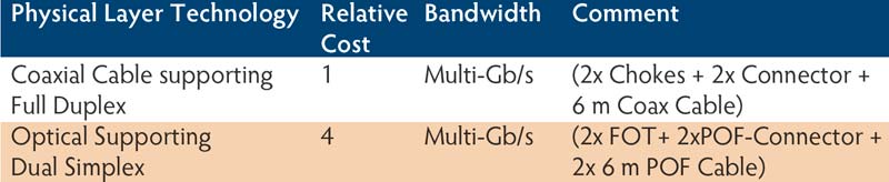
Table 2: Cost comparison between different physical layer technologies
The advantages of adopting a high-speed networked infotainment system based on coaxial physical layer are obvious. Adoption of this technology by OEMs will begin rolling out this year and we suspect the market to embrace it with open arms.
References:
Maarten Kuijk, Microchip, MOST-Forum-2014-p03-Eqcologic.pdf
https://de.wikipedia.org/wiki/Koaxialkabel
Terence Rybak and Mark Steffka,
Springer, Automotive Electromagnetic Compatibility (EMC)
https://archive.org/details/springer_10.1007-b101849
Author: Carmelo De Mola,
Product Marketing Manager
![]()