


 Cloud services are driving significant advancements in data center, networking and telecom equipment. The Internet of Things (IoT) already has more devices with Internet Protocol (IP) addresses connected to the cloud than there are humans beings on the planet. All of this growth greatly impacts the servers, storage, and networking switches that process an ever-increasing amount of data and video. It’s pushing infrastructure equipment to the limit in terms of processing power and bandwidth. For power designers, the main challenge is how to efficiently power and cool this equipment, while ensuring minimal electricity usage. Designers also must balance board power footprints with thermals when using today’s advanced processors, ASICs and FPGAs.
This article examines how multiphase converters have evolved to address these challenges, and compares different control mode schemes. It also presents a new multiphase architecture that leverages synthetic current control to provide cycle-by-cycle current balancing and faster transient response.

Figure 1: Multiphase solution using four phases
Multiphase Evolves to Power IoT
Processing power is centralized in data centers where high-end CPUs, digital ASICs, and network processors run servers, storage, and networking equipment. And they are distributed across the network through telecom equipment, and occurring at the point of transaction with point of sales machines, desktops or embedded computing systems using CPUs or FPGAs.
What all of these devices have in common is that their digital processing needs have a similar power profile. With shrinking processor geometries and increased transistor count, processors are now requiring higher output currents that can range anywhere from 100A to 400A or more. Figure 1 illustrates a multiphase solution that utilizes four phases to provide 150A to the CPU.
While this trend has persisted for years, the industry has been able to adapt by integrating lower power states into the digital loads. This allows them to idle at lower currents, and then peak to full power when demanded. While beneficial to the overall system power budget, it adds another challenge to the power designer. The full load current in excess of 200A still needs to be delivered and thermally managed, but now the supply has to react to the demand of a large load step of over 100A in less than a microsecond while keeping the output in a narrow regulation window.
The common solution has been to use a multiphase DC/DC buck converter to provide the required power conversion, typically ~1V output from a 12V input. To provide the large load currents, it’s easier to design a multiphase solution splitting the load across smaller stages (called phases) rather than delivering it via one stage. Attempting to handle too much current in one phase presents challenges in designing the magnetics and FETs, as well as managing thermals, from a (I^2)*R perspective. A multiphase solution offers high efficiency, smaller size and lower cost than a single stage for high currents.
This approach is analogous to the technology direction taken by the end loads where multicore CPUs divide the workload.
The Right Control Scheme
While multiphase solutions provide the best power architecture, the implementation needs to be carefully evaluated to match up with the latest generation of processors. The trend with end systems has always been enhanced features, smaller size, and improved power management. This is reflected in power designs increasing their switching frequencies to minimize size and manage lower output voltages with higher current in full load and transient conditions. These trends have presented problems in how power supplies are regulated, requiring control loops to evolve over time to keep pace. The key challenge in a multiphase controller is managing the current in each phase, which requires considering these key points:
• Each phase current must equally share the load. If N number of phases exist, the current for each phase should be Iphase = Iout / N at all times.
• Phase currents must be balanced during steady state and transients.
It is important to maintain these conditions; otherwise, you’ll be stuck overdesigning your power supply. To meet the two conditions noted above, it’s important that the control loop have full knowledge of phase currents and the output voltage at all times, without latency or sampling delay.
Enter Synthetic Current Control
A new approach solves the problem of current sensing, as opposed to avoiding the issue using workarounds in voltage control. Renesas’ breakthrough was made possible by utilizing state of the art, digital control technology. Advanced control methodologies could be applied by moving the entire control, monitoring and compensation into the digital domain. The result is a synthetic current control loop that provides cycle-by-cycle phase current balancing with fast transient response.
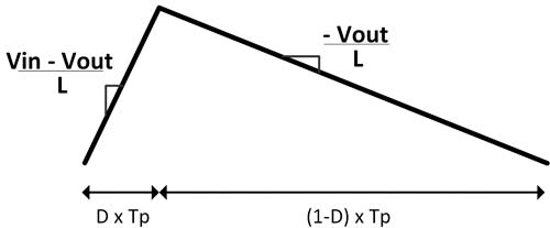
Figure 2: Inductor current waveform
The genesis of the new control scheme was the realization that while the high-side current signal is critical in the loop, it is not possible to measure directly due to the short on-time and high noise environment. Instead, Renesas’ new multiphase controllers use a synthetic current signal that’s artificially generated, giving it the benefit of being noise-free and accurate with zero latency. The basic principle is that all the parameters involved in determining the phase current can be measured directly each cycle, allowing the controller to derive the current, as shown in Figure 2.
The current waveform slope is related to the input/output voltage and the inductance. By continuously measuring the voltages and calculating the inductance, a synthetic current waveform is generated. Calibrating via real measurements on the current downslope allows the controller to eliminate any error because of current offset or slope.
This allows the controller to compensate for any system changes as a result of aging, thermal or inductor saturation. In addition to the internal noise-free current waveform, the controller can be positioned to account for loop latency. Since the inductor current ramps are timed to the PWM, whose signal is sent from the controller, the digital loop can account for all the propagation delays through the smart power stages, thereby eliminating latency in the internal current waveforms.
This capability is just one of the benefits that can be leveraged by having the entire loop control in the digital domain with current and voltage information. The Figure 3 block diagram shows that digital signal processing can be applied in various areas to improve overall response. The voltage loop compensation is applied using conventional PID coefficients, which can be adjusted real-time via Renesas’ PowerNavigator™ GUI.
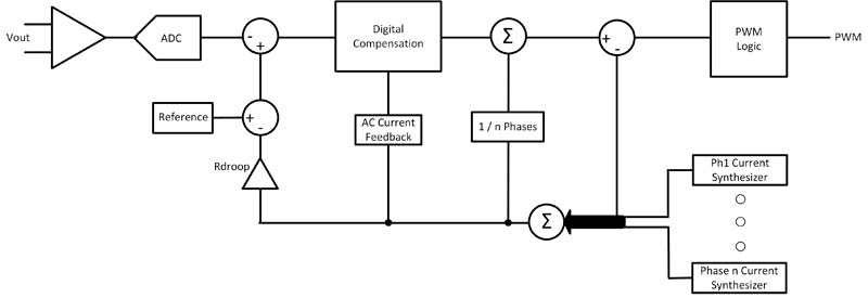
Figure 3: Block diagram of control loop
The Synthetic Control Advantage
With synthetic current control, a multiphase power supply’s current in each phase is known precisely, allowing it to maintain stable operation under continuous load transients, where all phases equally share current. Combined with zero latency in current feedback path, synthetic control enables the device to respond faster to load conditions, minimizing output capacitance. Even with high current CPUs, it is possible to utilize an “all ceramic” output capacitor solution. With zero latency, full bandwidth, digital current waveforms, the control loop can position the output voltage exactly according to the load line, mimicking the exact response of the load profile. This avoids the traditional analog RC decay that is seen in output voltages as they settle to the new target voltage.
Conclusion
The multiphase control architecture has evolved to solve the challenges of powering high current loads. It can adjust, control and monitor every setting via software. From a high level, this provides a simpler approach for designing and tuning loops. The ability during board debug to instantly understand the status and condition of the power supply, along with compensating for noisy conditions provides the peace of mind that any challenge can be met without re-design.
References
• Learn more about the digital multiphase controllers
• Watch an overview video

About the author
Chance Dunlap is a Senior Director at Renesas Electronics. Chance received his BSEE from Purdue University and MBA from the University of Arizona.
Renesas Electronics Corporation