


 First, the CPU is not needed for communication between peripheral and peripheral. The core can sleep and the software flow doesn’t need to be interrupted. Obviously, if the core is in sleep mode and software is not needed then the current consumption of the application will be lower. The CPU is the part of the microcontroller which has the highest current consumption. Therefore, using CIPs reduces power consumption.
Second, CIPs do not cause interrupts which allows for much faster communication overall. If the CPU core is running software and it has to be interrupted from the peripheral to accomplish a specific action, it requires a lot of time. The interrupt needs three clock cycles + two clock cycles for the relative jump and might use several cycles for the context switch, in order to save the data in the registers on the stack depending on the application. CIPs allow communication to be much faster than if the core has to be interrupted.
Third, using CIPs means faster time-to-market. Less software has to be written as the hardware can do the task on its own. This reduces the risk of software errors and less software validation is needed. Therefore, the development time of the product is shorter than without using CIPs.
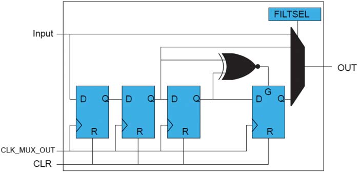
Figure 1: Filter of the CCL
In AVR® microcontrollers (MCUs), all Core Independent Peripherals are connected via the Event System. In the Event System, a multiplexer connects the event generator and the event user. There are synchronous and asynchronous events. Asynchronous events need less than one clock cycle and synchronous events need two clock cycles.
Many peripherals can be connected to the event system to be CIPs. These are timers, the Real Time Counter (RTC), Periodic Interrupt Timer (PIT), the Custom Configurable Logic (CCL), Analog Comparator (AC), Analog-to-Digital Converter (ADC), Universal Synchronous/ Asynchronous Receiver/ Transmitter (USART) and the General Purpose Input/Outputs (GPIOS).
Using the Core Independent Peripherals
Core Independent Peripherals need to be configured once before they are used. The CPU executes the instruction to do the right initialization of the Event System and the needed peripherals.
Delay/Debouncing
Several applications nowadays still use a button as an input. For every button a debounce logic or piece of software is needed to get a non-toggling signal. For the AVR MCU, it is an easy task to do the debouncing as software. This can be done by delays and/or logic in the software program. The software is not complicated but it uses CPU resources. Whether the button has been pressed or not can be checked either by polling or via an interrupt from the GPIO controller. Both need time and CPU usage to do the complete debouncing task.
Debouncing / Delay with the filter of the CCL
With Core Independent Peripherals, completing the debouncing task can be done without any additional overhead of the CPU. All that is needed is the Custom Configurable Logic (CCL). The GPIO, where the button is connected is configured as an asynchronous event generator. The CCL will be the event user. The signal from the GPIO pin to the CCL input will be transferred with no delay. The truth table in the CCL is configured so that the output is equal to the input. The output of the truth table is routed to the filter. For the filter of the CCL, see Figure 1. It is possible to remove glitches from the input signal and we can set the delay of the filter to two to five clock cycles (peripheral clock or an alternative clock) for the output signal. If we use a slow clock of 32 KHz than we have a delay of 1.5 ms. It is also possible to extend the delay time with a different clock or with a timer.
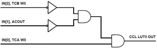
Figure 2: CCL LUT 0 Dead Time Generation
Delay with a Timer
For example, Timer/Counter B (TCB) is set up in “Single-Shot” mode. If the timer gets an event signal it starts counting until it reaches its programmed max value and stops it. The output of the TCB is connected to the CCL. In the CCL the desired combination of the delay signal can be done.
This allows for a very flexible time delay. Every new event to the TCB timer starts the counting again.
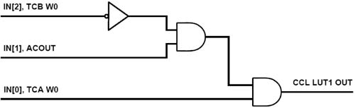
Figure 3: CCL LUT 1 Dead Time Generation
Dead Time Generation
Dead time is used in applications where switches (transistor, FET or IGBT) are in series between power and ground (GND). If both are activated at the same time there is a short. An example is an H-bridge configuration commonly used for motor control drive. Depending on the application the dead-time will either be between commutations or between the Pulse-Width Modulation (PWM) pulses. Dead time between PWM pulses is needed, for example, in sinusoidal drive and between commutations in 1-pole Brushless DC (BLDC) motors. Dead-time between PWM pulses can be generated with the timer Time Code Display (TCD).
To generate dead-time between commutations we need two timers, the Custom Configurable Logic (CCL) and the AC. Figure 2 and Figure 3 represent the logic of the truth table of the CCL.
The timer TCA generates the base PWM signal for the motor control. The AC is externally connected to the hall sensor of the motor and internally connected via the event system to timer TCB. Timer TCB generates the dead time signal if it gets a signal from the AC. The CCL combines the TCA (PWM), TCB (dead-time) and the AC signal. The input signals can be selected directly in the CCL configuration and do not need to use the Event System.
There are hardwired connections between these modules. The CCL then generates two PWMs, see Figure 4 which drives the switches for the motor. The motor runs without any CPU involvement. For more technical information see the AVR Application Note AVR42778.
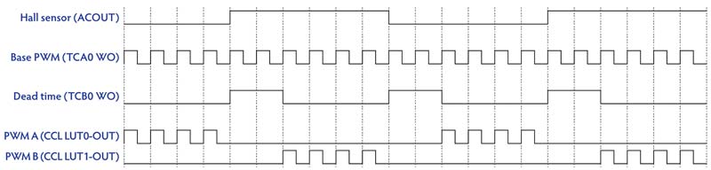
Figure 4: Timing Diagram of Dead Time Generation
Automatic Shut-off PWM Signal
Many applications need to monitor the current consumption so that it does not exceed a maximum level. This can easily be done with the analog comparator AC. The AC measures the voltage (current in the resistor) via a shunt register.
If it exceeds a previous configured threshold then the PWM signal should stop immediately. Both examples below are using Core Independent Peripherals. The PWM output signal can be stopped when an over current is detected without interaction of the CPU.
Example of LED Lightning with TCA and CCL
The Timer/Counter A0 generates the PWM for the Light Emitting Diode (LED). The AC is used to detect the overcurrent and the CCL is used to combine these signals, so that if there is an overcurrent detected then the PWM is automatically stopped. The AC and the TCA0 are connected via the Event System to the CCL. The AC output signal and the PWM are configured in the TRUTH table of the CCL, see Figure 5. The PWM signal is fed through if the event signal form so the AC is zero. If the over current is detected, the AC event signal is one and the output is zero as long as there is an overcurrent.
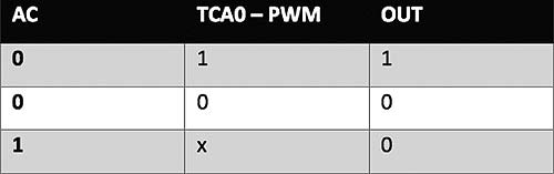
Figure 5: CCL Truth-Table for Fault Handling
Example of Motor Control with the TCD
A BLDC motor is controlled by the TCD timer that generates the two channels + two complementary channels PWM signals to drive the four Metal-Oxide Semiconductor Field-Effect Transistor (MOSFETs) in an H-bridge. The AC is used to detect the overcurrent in the motor with a shunt between the motor and GND. The AC is connected via the Event System to the Timer/Counter D0 (TCD). The TCD features include fault handling. If the threshold of the AC is exceeded (over current detected) then an event is signaled to the TCD and the PWMs are stopped automatically.
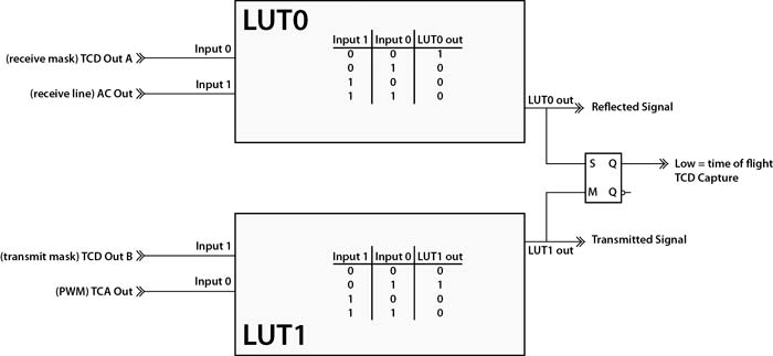
Figure 6: Ultrasonic Time of Flight Measuring
Measuring Time-Of-Flight
Time of flight measurement is used to measure the distance a signal travels. The measurements starts when the signal leaves the transceiver and stops when it’s detected by the receiver. With the time and the known m/s of the signal the distance can be calculated. In the below example we are measuring the distance with ultrasonic signal. For that we need the Core Independent Peripherals TCA0, TCB0, TCS0, AC and 2x CCL and can compute the time of flight without CPU usage.
Figure 6 shows the look up Table 1 (LUT1) generates the Transmitted Signal. TCA Out generates the PWM signal and TCD Out B is the transmit mask. The inverted transmit mask and the PWM are logic AND combined and then generate the transmit signal, which is shown by the LUT1 truth table.
LUT 0 generates the reflected signal. AC Out gives the activity on the receive line and TCD Out A is the receive mask. The inverted receive mask and the “receive line” are logic AND combined generate the Reflected Signal, which is shown by the LUT0 truth table.
The SR latch is reset with the first transmitted signal and starts the counter in TCD. With the signal from reflected signal and when the SR latch is set, the TCD counter is stopped. The time of flight is now stored in the counter value of TCD without any use of the CPU. The CPU is only needed for the distance calculation where the time of flight is multiplied with the speed of the signal. For more technical information for ultrasonic distance measurement see the AVR Application Note AVR42779.
Conclusion
The new ATtiny1617/1616/1614/817/816/ 814/417 microcontroller series from Microchip adds innovative Core Independent Peripherals (CIPs) to the tinyAVR® family of microcontrollers. With these CIPs, an application can react in real-time, with less software overhead and lower current consumption than without CIPs. These examples show that CIPs are easy to set it up and that the real-time performance is faster and needs less power consumption than software-based solutions. Even with much higher performance microcontrollers this level of real-time performance cannot always be reached and, if possible, the power consumption would be several times higher.
References
• Further information of the new tinyAVR family:
• AVR ATtiny817 webpage
• AVR42778 Application Note: Core Independent Brushless DC Fan Control Using Configurable Custom Logic on ATtiny817
• AVR42779 Application Note: Core Independent Ultrasonic Distance Measurement with ATtiny817
Author: Gregor Sunderdiek, Business Development Manager MCU8 EMEA
![]()
Microchip Technology
www.microchip.com