

The benefit of using integrated LCD displays in an application is that it enables data to be shared with the user in real time. In addition, the LCD can display more information vs. a standard pressure, temperature gauge or electromechanical meter that in the past had been included on thermostat meters and health equipment.
As well as the medical sector, LCD usage is increasing in a wide range o findustrial and consumer applications, from Building Control including Heating, Ventilation and Control (HVAC) applications, metering applications, from gas, water to electricity meters, to measurement devices, home appliances such as coffee machines, as well as peripheral applications like docking stations and audio devices. These applications share some common requirements as far as the microcontroller is concerned: LCD capability, low power consumption and the ability to control and measure the environment.
Flexible LCD Solution
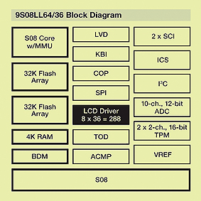
Taking into account these demands, Freescale has developed the MC90S08LL family, which is based on 8-bit HCS08 architecture. The family provides flexibility and the capability to drive high segment count LCDs via fewer pins and smaller packages, thereby saving space and enabling a more cost effective solution. A key advantage of the family is that it can drive up to 192 segments on an LCD panel, while only using 32 dedicated pins. For size-constrained applications, this means a smaller PCB footprint, lower system cost through smaller PCBs and smaller more cost-effective microcontrollers. The LCD controller has up to 32 dedicated LCD pins supporting up to 26 front-planes (FP) and 8 back-planes (BP). The 26 FP pins can be multiplexed and function also as a BP pin, meaning the total segment support equals front-planes (26) x back-plane pins (8). Another feature of the LCD controller is the capability to blink an LCD segment in stop mode. Developers have the capability to blink all LCD segments or program independent LCD segments to blink. There are multiple programmable options for blink mode, including blink rate. The blink functionality is available in the low power Stop3 mode as well as the Run, Wait, Low Power Run and Low Power Wait Modes. This blink capability is enabled by an integrated charge pump, which holds the voltage constant to the LCD even though the voltage to the part is reduced, effectively acting as an onchip capacitor.
The main benefit of the flexible blink option is that saving power LCD segments can still blink to represent a counting signal in the application or while a measurement activity is underway.
Low Power Operation
In many applications that require LCDs, low power is also a key factor. For handheld and portable applications, power consumption is critical to maximize battery life. Other applications are typically powered via a mains supply, however if power is cut, a battery backup system is required. For metering systems, power consumption is an especially critical factor and many utilities companies are stipulating that a meter must be able to run off a battery for up to 10 years. A range of design and manufacturing techniques, as well as modules on chip to control clocking, enables the MC9S08LL family to deliver a true low power microcontroller solution.
Clock Selection
The MC9S08LL’s heart is the internal clock source module (ICS). This module enables designers to select an external reference clock from 32KHz up to 16MHz or an internal reference clock that is trimmable from 31.25kHz to 39.06KHz. The core of the ICS module is the frequency lock loop (FLL) block, which multiplies the input clock up to a maximum 20MHz CPU speed. The external reference clock can be as high as 16MHz and can be divided by a reference divider (RDIV), which is programmable from 1 to 1024.
The FLL can also be bypassed if a low frequency bus is required. A second divider block, bus frequency divider (BDIV), can divide the clock signal down by one, two, four or eight before it is sent to the rest of the device as the ICSOUT signal. The ICS also controls an independent 1KHz very low power oscillator (LPO), which can be used by the RTC (real time clock) and the watchdog. The key to the MCU’s flexibility is the ability to use the internal oscillator and the external oscillator source for different modules at the same time. This means that by running some modules slower than others, power consumption can be reduced.
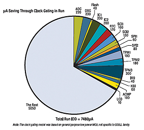
The system clock gating control registers gate the clock source to the timers, ADC, inter-integrated circuits (I2Cs), serial communication interfaces (SCIs), debug module, fl ash memory, external interrupt request (IRQ), keyboard interrupt module (KBI), analog comparator, time of day (TOD) and serial peripheral interfaces (SPIs). Gating the clock off the clock to unused modules saves power in the MCU’s Run and Wait modes. Gating modules on only when needed and gating them off when the task completes is a significant power saving technique.
Modes of Operation – CPU
Choosing the right mode at the right stage of operation of the system can make or break the product’s power consumption targets. Exit paths, wake up times and register retention are all choices that the system designer has to make. Along with the usual run mode, the MC9S08LL has five other power saving modes. Three of them, Wait, Stop 3 and Stop 2, are not new to the S08 core and are common in other devices, although perhaps under different names.
There are two new key power saving modes that have been take from the Ultra-Low-Power MC9S08QE family and added to the MC9S08LLdevices – Low Power Run (LPR), saves power compared to normal Run mode by placing the voltage regulator into standby. To enter this mode, FBELP, the lowest power ICS mode, must be running. The low voltage protection system must be disabled along with the MCU’s internal band-gap and the on-chip in-circuit emulator/ background debug controller (DBG/ BDC) modules, as all three modules consume significant amounts of power, regardless of the bus frequency. Since the voltage regulator is in standby, every opportunity to keep the power down in this mode is recommended. Low Power Wait (LPW) mode can only be entered from the LPR mode and as such the restrictions on LVD circuitry, debugging and ICS mode are the same. The MCU can typically save 50 percent of its current consumption in LPW versus LPR.
• Run mode: CPU clocks can be run at full speed and the internal supply is fully regulated
• LPRUN mode: CPU and peripheral clocks are restricted to 125 kHz maximum and the internal voltage regulator is in standby Wait mode: CPU is not clocked.
System clocks are running and full regulation is maintained
• LPWAIT mode: CPU is not clocked, peripheral clocks are restricted to 125 kHz maximum and the internal voltage regulator is in standby
• Stop3: CPU is not clocked. Voltage regulator standby & peripherals are not clocked but are powered for fast recovery
• Stop2: CPU and peripherals are not clocked. Voltage regulator is in partial power down, RAM content is retained, I/O states held.
Other MCU Features to Help Save Power
As with all Freescale microcontrollers 1.8V to 3.3V devices, the fl ash memory is reprogrammable down to 1.8V, which helps extend battery life in portable applications. An additional three ports on the MC9S08LL device have Set, Clear and Toggle capabilities, which can speed up pin manipulation, reducing code execution time so low power modes can be re-entered quickly. All of the device’s output pins have slew rate control, which, when driving external components, can reduce power by slowing transients and drive strength control.
HCS08 products incorporate SuperFlash® technology licensed from SST.
The article has been supplied by Farnell in cooperation with Freescale.
www.farnell.com
www.freescale.com