


Introduction
The realtime requirements of microprocessor interfaces lie in the range of mere microseconds, if not nanoseconds. Conventional microprocessors are largely operated using a high-level operating system (HLOS), such as Embedded Linux or Windows Embedded CE. However, this makes it very difficult to achieve a deterministic reaction time of less than one millisecond in the user application or kernel driver, and significant effort is necessary.
To achieve the necessary reaction times for a realtime interface, it is necessary to decouple the HLOS using a dedicated peripheral block. The interface in question is typically made available by the manufacture in hardware on the microprocessor (UART, SPI and I2C are examples). If no appropriate interface is available on the microprocessor, the realtime requirement must be decoupled from the HLOS using an external application-specific integrated circuit (ASIC) or a field programmable gate array (FPGA) providing the corresponding functionality.
Above all, the industrial sector presents an enormous range of complex applications with realtime requirements. The developer can only provide the interface necessary to meet these requirements using an external ASIC or FPGA. This means using more space on the board and additional component costs. The Texas Instruments (TI) AM1808 ARMTM microprocessor offers an alternative solution. This article describes a method that integrates the realtime requirements of an interface back into the microprocessor, without needing an ASIC or FPGA.
The Programmable Realtime Core in the AM1808
The AM1808 is a low-power ARM9 microprocessor based on an ARM926EJ-S™ RISK core, and may be clocked at up to 456 MHz. It includes a range of valuable on-chip peripherals, which may be usefully deployed in industrial applications:
a 10/100 Mb/s Ethernet MAC (EMAC) with Management Data Input/Output (MDIO), USB interfaces, I2C interfaces, multichannel audio serial port (McASP) with 16 serializers, multichannel buffered serial ports (McBSP), SPI interfaces, 64-bit timer, host port interface, UARTs, enhanced PWM module, enhanced capture module, GPIO , LCD controller, connection to external memory, and asynchronous external peripheral modules.
An important distinguishing feature included in the peripheral devices is the programmable realtime core (Programmable Realtime Unit, PRU). It can access all system resources independent of the ARM core. The PRU may be freely programmed by the developer and is ideal for realtime interface, Layer 2 protocol processing and proprietary manufacturer protocols. Particularly in the field of industrial applications, which are distinguished by a large number of different interface protocols, the implementation of the realtime interface in the PRU may result in savings on external hardware components.
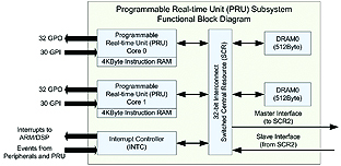
The following diagram shows the PRU Subsystem (PRUSS):
The PRUSS contains two PRU cores consisting of independent 32-bit RISC processors with their own instruction and data memory. They are clocked at half the frequency of the ARM core. The zero-stage pipeline on the instruction memory allows the PRU to execute all commands in a
single cycle. So, if the ARM core is clocked at 456MHz, each PRU will run at 228MHz, which corresponds to a command cycle time of only 4.4 ns.
Knowledge of the command cycle time makes it possible to calculate the execution time of program algorithms in the PRU, and thus also to implement interfaces with realtime requirements.
Register Addressable Inputs and Outputs
The PRUs feature 30 inputs and 32 outputs, which are addressed directly using
registers. These inputs and outputs are tapped over the microprocessor pins after pin multiplexing for external signals has been configured in the AM1808. This allows each PRU to switch external signals within just a few nanoseconds and react
to external signal changes with service routines. Application examples include reading in data after an external event, serial log generation with clock and data links and the connection of external modules.
Interrupt Controller and System Events
Another component of the PRUSS is an interrupt controller (INTC) through which each PRU event (interrupt) can be received by on-chip peripherals and the ARM core. If an event is triggered by the on-chip peripheral, it will be registered in the INTC and evaluated in the program flow in the PRU. This means that even complex protocols interacting with the on-chip peripherals can be implemented in the PRU. The serializers included with the McASP/McBSP ports are an example of this: The PRU processes the Layer 2 protocol on the byte level and uses the serializer ports for physical input and output.
The bit-test command allows each PRU to check whether an event was triggered. Evaluating the event number in the PRU then makes it possible to call the proper service function. The service function then returns a receipt for the event in the INTC to allow reception of the next event.
8 system events are additionally available in the INTC to trigger interrupts in the ARM core. These system events exist for effective inter-process communication (IPC) between the PRU and the ARM, avoiding unnecessary polling.
Internal Bus Architecture
Each PRU can also act as an independent bus master, just like the ARM core and the EDMA controller. This means it is capable of accessing all system resources mapped in memory, e.g., internal and external memory, UART, McASP, timer, and all other peripherals available to the system. To guarantee data consistency, each peripheral block should only be used by one bus master. The Linux kernel allows for resource allocation to prevent such dual use. The IPC is an exception, as data exchange takes place over a shared memory range.
The internal bus architecture (Switched Central Resources, SCR) of the AM1808, which is used to connect all master and peripheral devices with one another, allows for the parallel execution of multiple bus transactions without the bus masters blocking one another. This means the PRU can access internal memory and the ARM core external memory without reducing memory throughput.
Programming the Realtime Unit
The PRU is programmed in assembly language. Over 40 assembler commands are available for this purpose. They cover arithmetic, logic, flow control, memory access, bit and packet manipulation, and pattern search functions using a number of registers. In the AM1808, each PRU has 4 kB of instruction memory for up to 1024 assembly commands. The PRU program is loaded into instruction memory and started either by the ARM core, the EDMA controller or the second PRU. The PRU can be stopped at any time and loaded with a new program. This makes it possible to cover multiple functions with the PRU, dynamically loading them depending on the current application requirements. The PRUSS provides control registers to start and stop the PRU core. Another register provides information on the number of processed PRU command cycles.
PRU Implementation Example:
Data Acquisition and Digital Reduction Filter for a Delta-Sigma Modulator
Implementation of data acquisition and a reduction filter in the PRUSS allows a low-cost delta-sigma modulator to be employed in the solution presented here.
A delta-sigma modulator returns the average value of a time range Δt.
Oversampling in the modulator means several data values are required to generate a single output value.
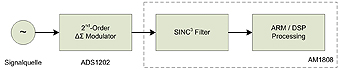
Many cases see the use of a SINC filter – an easy-to-implement and cascadable low-pass filter (see the application brief at: http://focus.ti.com/lit/an/sbaa094/sbaa094.pdf). The modulator is suitable for low-frequency data acquisition, e.g., temperature measurements, audio signal processing or current flow metering at motor PWMs and generators.
The ADS1202 delta-sigma modulator used in this example has a dynamic range of 80 dB with an effective 12-bit resolution at 10 kHz signal bandwidth. while oversampling takes place at 10 MHz. It is operated with a 5V supply. Its differential inputs allow sampling at transducers/magamps and low-voltage signals.
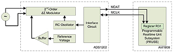
The delta-sigma modulator is connected to the PRUSS using the data (MDAT) and clock (MCLK) lines to two input bits mapped in register R31. The bit-test command (QBBS – Quick Branch Bit Set, jump when bit is set) allows the PRU program to query the status of an input in a single clock cycle.
The delta-sigma modulator delivers a new sample bit every 100 ns by oversampling the 10 MHz input signal.
The sample bit must be fetched and processed by the PRU within this period of time before the next sample bit from the delta-sigma modulator is ready. If this does not occur, sample bits will be lost and the measured value distorted.
A PRU clocked at 225MHz can execute 22.5 commands during this 100 ns period.
The implementation of data acquisition and filtering may not exceed this command budget.
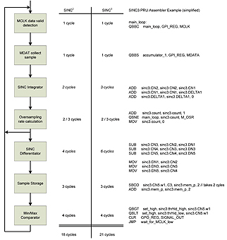
The following functions are implemented in the PRU:
1. Wait for the next valid measured value to become available: Test the MCLK bit in register R31 for a transition from 0 to 1. This event triggers the following steps.
2. Process the MDAT bit sample from register R31 in the SINC filter integrator step.
3. Call the SINC filter differentiation step, depending on the selected reduction value (oversampling rate).
4. Save the measured value in local memory and, if necessary, signal event to the ARM for further measured value processing.
5. Test the measured value for min/max limit exceedance.
The diagram lists the individual PRU tasks and compares the number of commands necessary between SINC2 and SINC3 filters. The assembler commands for the SINC3 filter implementation are also displayed in a simplified form.
The first four functions are carried out for every sample. This part uses six (for SINC2) or seven (SINC3) commands from a budget of 22.5 commands per bit sample. Depending on the selected oversampling rate, the program either waits for the next sample bit or calls the SINC filter differentiation step. The next measuring result only becomes ready for further processing after the SINC filter differentiation step. For this reason, the measured value min/max check and saving the sample to local memory only takes place after this step. In this example, it can be recognized that a SINC3 filter implementation with 21 commands uses almost the entire budget – to reduce the budget load, the min/max check can be postponed to the next sample bit cycle, which will only require seven cycles.
Summary and Outlook
The programmable realtime core in the AM1808 makes it possible to implement customer-specific interfaces and protocols without any need for additional components. The realtime interfaces programmed by the PRUSS work independently from the ARM core. This allows the ARM core to run a HLOS such as Embedded Linux or Windows CE Embedded with access to the independent realtime interfaces in the PRUSS.
Other PRU applications include additional UARTs (SoftUART). The AM1808 already provides three UARTs as on-chip peripherals. However, certain applications such as an IO link master require 4 or 8 UARTs. In this case, the ARM core can work with the PRUSS and the McASP peripheral to make additional SoftUARTs available.
Mistral (www.mistralsolutions.com) offers a SoftUART driver for download from their website. It supports Linux and can run up to four additional SoftUARTs per PRU.
Mistral has also developed a CAN bus driver based on the PRUSS, which emulates a CAN interface using the PRU inputs and outputs. This is particularly well suited for customer-internal bus systems with reduced transmission speeds. The driver is available with documentation for download from Mistral on their website.
It is also possible to integrate complex realtime interfaces such as PROFIBUS in the PRUSS. TI already offers a certified PROFIBUS slave solution with the AM1810 microprocessor.
The PRUSS is also included in other TI microprocessors and digital signal processors (DSP). For more information on the PRUSS, see the TI Wiki Page, and the product pages for the AM1808, TMS320C6748 and OMAP-L138.
Links:
1. Combining the ADS1202 with an FPGA Digital Filter for Current Measurement in Motor Control Applications: http://focus.ti.com/lit/an/sbaa094/sbaa094.pdf
2. PRUSS Wiki Page: http://processors.wiki.ti.com/index.php/Programmable_Realtime_Unit_Subsystem
3. AM1808: http://focus.ti.com/docs/prod/folders/print/am1808.html
4. AM1810 with integrated PROFIBUS: http://focus.ti.com/docs/prod/folders/print/am1810.html
5. OMAP-L138: http://focus.ti.com/docs/prod/folders/print/omap-l138.html
6. TMS320C6748: http://focus.ti.com/docs/prod/folders/print/tms320c6748.html
www.ti.com