By Ajinder Singh, Product Definition, Texas Instruments
High-end, cool smartphones and the ecosystem around them are symbolic of the fact that consumers want mobile broadband and applications that can help them connect to information,
family and friends seamlessly. Thus, mobile broadband is clearly today’s growth engine for the telecom industry.[1, 2] Telecom operators have seen huge growth in wireless data revenue in recent years despite the economic slow down. Meteoric growth in netbooks and HSDPA-USB dongles is also an indication that consumers want mobile broadband, not only in their homes and offices, but
anywhere they go.
Missing in the mobile Internet today is the “wow” experience. Consumers still get discouraged by download speeds or degraded graphics while accessing data on their mobile devices. Applications such as video blogging and online gaming rely on faster connectivity and lower
latency. Faster and reliable connectivity will help exploit the applications built around cloud computing and, thus, make our mobile office experience not limited by the mobile device’s hardware processing capability.
Mobile operators are counting on the fact that even now, out of the 4.3 billion wireless users, approximately 80 percent are voice-only GSM users. Thus, the growth opportunity over the next five to ten years is to capture three billion users who can subscribe to mobile broadband.[2] Growth can also potentially come from another set of devices like IPTV, digital cameras, etc., that have mobile broadband connectivity and can enable new services, generating more revenue for mobile operators.
To keep up with the surging demand to provide faster and reliable connectivity with lower latency, network operators around the world expect to roll out 4G networks, and long-term evolution (LTE) is the global front runner.
• Sometimes LTE also can be termed as fourth generation (4G), and is designed to increase the capacity and speed of mobile telephone networks. The LTE specification provides downlink (forward link) peak rates of at least 100 Mbps, an uplink (reverse link) of at least 50 Mbps, and radio access network (RAN) round-trip delays of less than 10 ms.[1]
• LTE also leverages advanced antenna technology concepts like beam forming to enable extended coverage. High peak-data rates can be achieved with multilayer antenna solutions such as 2×2 or 4×4 multiple-input multiple-outputs (MIMO).
Having all the great features of a new standard is one thing, but wireless and mobile network operators face the continuing challenge of investing capital and building networks that are somewhat “future-proof” in meeting the exploding demands on bandwidth. Network operators must choose the most cost-effective evolution of the networks towards 4G. Network upgrades required to deploy networks based on 4G standards like LTE must not only balance the limited availability of new spectrum, but also leverage existing spectrum.[3] To manage the evolving complexity of the standards efficiently, a concept of distributed open base station architecture has evolved in parallel with the standards to provide a flexible, cheaper and more scalable modular environment for managing the radio access evolution.
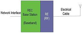
Traditional base station deployment as shown in Figure 1a requires the radio equipment control (REC) and radio equipment (RE) to be co-located with the antenna tower in a single enclosure. This approach proved to be detrimental to the network providers in terms of the large footprint, high power and ultimately high cost of its deployment.[6] This kind of architecture also leads to signal loss over the electrical cable that connects the antenna to the RE.
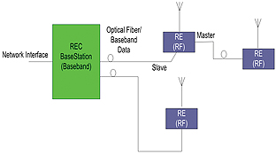
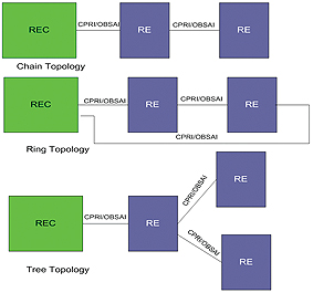
The distributed base station architecture (DBSA) in Figures 1b – 1c eliminates the dependency of the RF transceivers on the rest of the base station. This architecture allows the RE to be relocated next to their respective antennas, which minimizes the electrical loss between the RE and the antenna shown in Figure 1b, reducing the cost of RF power amplification. DBSA also allows various RE network topologies, for example chain, ring or tree as shown in Figure 1c. This approach ensures a relatively low network deployment footprint since the radio equipment can be networked with one another without requiring each RE to communicate to an REC.
The Open Base Station Architecture Initiative (OBSAI) and the Common Public Radio Interface (CPRI) standards address the baseband data communication between the radio equipment control and radio equipment, as well as radio equipment networking in DBSA. By standardizing the interface between REC and RE, the REC and RE equipment from different vendors can be mixed and matched. At the same time, a 2G/3G/4G-capable REC can communicate with different RE, thus allowing combined and concurrent multi-standard operations and reducing equipment upgrade needs.[3]
Both CPRI and OBSAI specify a high-speed serial interface between the radio equipment control and radio equipment, capable of baseband data transport (I/Q data), as well as communicating command/control and synchronization (for RE networking) information over the same interface.
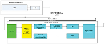
Figure 2 shows signal flow in a DBSA. Looking at the RE in the forward link, the OBSAI/CPRI data is recovered by a serializer / deserializer (SerDes), which converts the high-speed serial data to parallel data and passes this data to an FPGA. The FPGA processes the OBSAI/CPRI logic and passes the I/Q baseband samples to a digital up-converter (dedicated logic), which modulates the I/Q baseband samples onto a digital IF carrier. The up-converted data is then passed through a data processing engine to reduce the crest factor (dedicated logic) and to digitally predistort (dedicated logic) the signal to compensate for side lobe generation in the power amplifier, as well as to ensure that the power amplifier can operate in the linear region.[4]
In the reverse link, the radio head contains all of the analog functionality to down-convert an RF band to an intermediate frequency and then digitally down-convert individual carriers to baseband in-phase and quadrature (I/Q) pairs of samples.
Multiplexed baseband samples (I/Q) along with control and management data in both the forward and reverse links are serialized and sent over the fiber optical cable via a SerDes device (for example, Texas Instruments’ TLK3134).[4]
Analyzing the DBSA with respect to the 4G evolution and the surge in demand to provide faster and more reliable data connectivity raises another concern. As the forward link and reverse link data rates increase and as more network subscribers move to high-bandwidth applications like on-demand TV, the serial data rate between the REC and RE also increases. The serial data rate (SDR) calculation between REC and RE[5] can be calculated using Equation 1:

[Equation 1]
Where,
SDR = Serial Data Rate between REC and RE
M = Number of antennas
Ac = Number of carriers/antenna
S = Sampling rate (sample/s/carrier)
N = Sample width, bits/sample
C = 8b10b overhead during serial transmission between REC and RE
Channel Bandwidth Sampling Rate
(MHz) (Msamples/s/carrier)
5 7.68
10 15.36
15 21.04
20 30.72
Table 1. Sampling rate required based on channel bandwidth
2(I/Q) = Multiplication factor of two to account for in-phase and quadrature-phase data
Using Equation 1 and Table 1, for a 20 MHz radio with four W-CDMA carriers, a two antenna system, sampling at 7.68 Msamples/s/carrier and with four bits/sample of I-Q sample width, the raw serial rate is shown in Equation 2:

[Equation 2]
Similarly, using Equation 1 and Table 1, for a four antenna LTE system, a one-carrier/antenna, 20 MHz LTE carrier sampling at 30.72 Msamples/s/carrier and with sample width of 16 bits/sample of I-Q data, the raw serial rate in Equation 3 is:

[Equation 3]
For an eight-antenna beam-forming LTE system, the SDR in Equation 3 would double to 9.8 Gbps. Hence, an increase in I-Q sample width, channel bandwidth, or number of antenna carriers directly contributes to an increase in the serial data rate between the REC and the RE. For network equipment manufacturers building infrastructure, it is important to realize that with the LTE evolution, the serial data rate must scale from modest rates of 614.4 Mbps to 9.8 Gbps or 12.2 Gbps. High SDR in the DBSA requires higher performance of the SerDes on both sides of the fiber optic cable for robust clock-data recovery and meeting the jitter specifications of the CPRI or OBSAI standards. To dig deeper into the SerDes and data processing expectations in
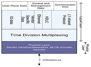
4G, let’s analyze the protocol stack of CPRI/OBSAI.
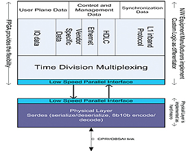
Figure 3a shows the CPRI protocol layer stack. Typically, the physical layer consists of fixed functionality, which is common across multiple protocols. The fixed functionality physical layer portion of the CPRI/OBSAI protocol layer is implemented as a hard macro to meet the stringent timing closure requirements. The logical layer, however, tends to be more customizable.[6] The logical layer is updated to keep up with emerging standard evolution, as well as the desire of network equipment manufacturers to create their own value-added features via proprietary functionality. An FPGA typically can provide the desired flexibility in implementing the logical layer portion of CPRI/OBSAI interface. The logic elements in an FPGA can be programmed to support a custom logical layer.
As network equipment manufacturers migrate towards the 4G deployment, they will face a situation where they still require not only the same flexibility to implement the logical layer, but also an increased SerDes performance to meet the increased SDR. Network equipment manufacturers have a choice either to buy an FPGA with integrated serdes or to buy an FPGA and discrete SerDes and interface them as shown in Figure 3b.
Let’s consider some of the key factors that can potentially determine the decision making of discrete SerDes-FPGA vs. integrated SerDes-FPGA:
• Cost of discrete SerDes + FPGA vs. Cost of FPGA with integrated SerDes
• Performance of a discrete SerDes vs. Performance of SerDes integrated in an FPGA
• Familiarity with a particular FPGA platform
• Area saving by moving to an FPGA with integrated SerDes.
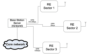
Figure 4 shows an example where a 2G/3G/4G capable base-station or REC is connected to three RE serving three sectors. The three CPRI links in this example are configured at 614.4 Mbps, 3 Gbps and 9.8 Gbps line rates, assuming that 9.8 Gbps is the updated SDR to support 4G.
CASE A: Consider a case where the network equipment manufacturer is using an FPGA with a discrete SerDes and has invested time and resources in the learning cycle for that particular FPGA platform. To support 9.8 Gbps in such a case:
• The manufacturer upgrades the SerDes and continues to use the same familiar FPGA platform. Advantages: Gets economy of scale, since all three RE sectors as shown in Figure 4 can have a similar FPGA, while still operating at different SDRs. This way the manufacturer does not have to change the FPGA platform and go through a learning cycle.
CASE B: The network equipment manufacturer uses a cost-effective low-end FPGA with integrated SerDes capability. To support 9.8 Gbps in such a case, the manufacturer has three options:
• Move to a high-end FPGA (integrated SerDes) with 9.8 Gbps capability from a different vendor. Disadvantages: Costs more and the manufacturer must go through the learning cycle of the new FPGA platform.
• Move to an FPGA (integrated SerDes) with 9.8 Gbps capability from the same vendor that competes on price.
Disadvantage: Performance concern.
• Partition the system into FPGA + discrete SerDes, by buying an FPGA without SerDes from the same vendor.
Advantages: Manufacturer saves cost by moving to an FPGA without Serdes, still keeps the familiar FPGA platform, also as an example in Figure 4, can partition all three RE sectors with discrete SerDes and drive economy of scale by using the same FPGA. Disadvantage: Potentially more PCB area for a discrete Serdes and FPGA solution.
CASE C: The network equipment manufacturer is using a high-end FPGA with integrated Serdes. To support 9.8 Gbps in this case, the manufacturer has three options:
• Move to an FPGA (integrated SerDes) from the same vendor but with 9.8 Gbps capability. Disadvantages: The manufacturer might have to pay the very high cost of the FPGA with 9.8 Gbps SerDes capability.
• Move to a low-end FPGA (integrated SerDes) from a different vendor, but with 9.8 Gbps capability. Disadvantages: Learning cycle, performance concern, lack of economy of scale to drive the cost low.
• Partition the system into FPGA + discrete SerDes, by buying an FPGA without Serdes from the same vendor. Advantages: similar advantages as Case B.
At a high SDR like 9.8 Gbps or 12 Gbps, meeting the robust clock-data recovery, jitter-tolerance, signal-conditioning and signal-integrity requirements poses design challenges even for a discrete SerDes design, let alone for an FPGA-with-integrated-SerDes design where noise isolation of sensitive analog circuits from the digital logic elements block (majority area of the die) poses even greater challenges. At times, to meet the required performance, an FPGA with integrated SerDes can require expensive power supply filtering and use of a voltage controlled crystal oscillator vs. a less-expensive crystal oscillator. These requirements add to the cost of implementation. In summary, there is a cost associated with Serdes-integration into an FPGA, and that cost will potentially go up as integration challenges increase with high SDR. This is one of the primary reasons why even today, at 3 Gbps data rates or lower, an FPGA + discrete Serdes solution is more cost-effective compared to the integrated solution.
Conclusion
As network equipment manufacturers build up infrastructure for 4G there will be an ever-increasing demand for high serial data rates between the radio equipment control and radio equipment in distributed base station architecture deployment. This increased demand will require higher performance from Serdes on both sides of the fiber optic cable. Network equipment manufacturers can partition their system, so that for the logic layer processing, they can use the same familiar FPGA platform. To meet the high serial data rate, they can upgrade only the Serdes portion by moving to a discrete SerDes solution. This kind of partitioning will deliver the required performance and save the learning cycle of moving to a new FPGA platform, as well as helping drive economy of scale and ultimately saving cost for the manufacturers.
References
1. LTE – an introduction: Long Term Evolution (LTE) offers a superior user experience and simplified technology for next-generation mobile broadband (White Paper), Ericsson, June 2009.
2. LTE – Top 12 Challenges, by Manish Singh, Continuous Computing, Wireless Week, September 18, 2009.
3. Remote Radio Heads and the evolution towards 4G networks, by Christian F Lanzani, Georgios Kardaras, Deepak Boppana, Altera Corporation, February 2009:
4. WiMAX & Wireless Infrastructure Equipment block diagram, Texas Instruments 2009.
5. Using signal compression to ease migration to a 4G wireless infrastructure, by Allan Evans, Samplify Systems, Programmable Logic DesignLine, Oct 20, 2008.
6. Supporting CPRI-Based Wireless Basestations with Cost Optimized FPGAs, by Van Macomb and Ron Warner, Lattice Semiconductor Corporation, dspstore.com e-newsletter, March 2009.
About the Author
Ajinder Pal Singh is a Systems Engineer, Interface & Clock Products, at Texas Instruments where he is responsible for business development and product definition for telecommunications. Ajinder has presented several papers on high-speed interface signal integrity issues at IEEE conferences. He has one patent pending in the area of High Speed Interface. Ajinder earned his MSEE from Texas Tech, Lubbock, Texas.
www.ti.com


