 Switching off an IGBT with negative voltage by using a unipolar power supply
The idea to work with a unipolar power supply to switch the IGBTs isn’t new. The problem so far was that the turn off voltage is 0V and not negative. Many designs failed in the past, because of parasitic turn on due to dV/dt in the system. The typical threshold voltage of an IGBT is around 6V. If a parasitic Voltage between Gate and Emitter occurs in the range of 6V the IGBT can turn on and lead to a system stop.
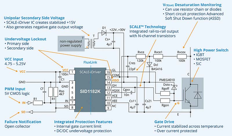
The SCALE-iDriver™ has an integrated voltage regulator for the turn on voltage. This means the supply voltage can be a unipolar and unregulated 22V-30V supply (Vtot). The SCALE-iDriver™ generates a regulated +15V voltage to turn on the IGBT. The turn off voltage is the difference of the supply voltage and the regulated +15V.
Example: Vtot = 22V → Voff = -(22V-15V) = -7V
 COST SAVINGS
• Using Simple Transformer (will be available from Power Integrations soon)
• Less Rectifiers for DC/DC needed
• No external voltage regulator needed
• No need of suppressor Diode for Gate Emitter protection (simple diode from Gate to +15V).
Reducing Isolation barriers of sensors with an reinforced isolated Gate driver (acc. to VDE0884-10/17)
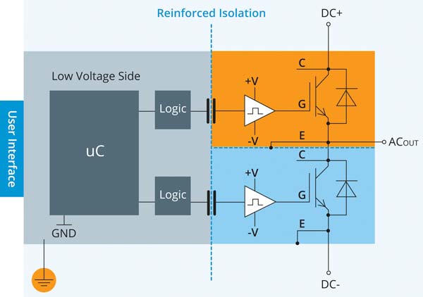
Most motor drives use engine speed sensor or current sensors to get a feedback of the motor state. From a cost perspective these signals shouldn’t be transferred over an isolation barrier to a Microprocessor which is connected to a high voltage. For cost optimization – and in most cases also technical wise – the best solution is a Microprocessor on SELV level (earth potential) like shown in the picture on the right side. But therefore a reinforced isolated gate driver is needed.
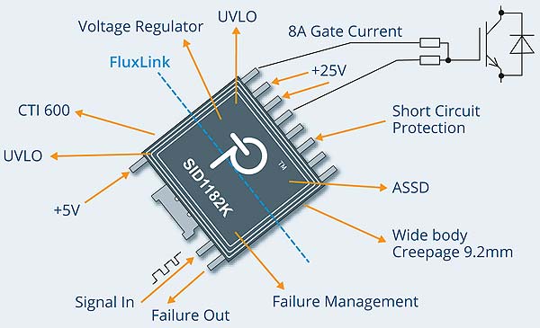
SCALE-iDriver™’s reinforced galvanic isolation is provided by Power Integrations’ innovative solid insulator FluxLink™. FluxLink™ is a magneto inductive technology to transfer the PWM command signals from the primary (IN) to secondary side. Thanks to this technology the SCALEREDUCE iDriver™ is providing safe isolation between primary side (LDI) and secondary-side also after the secondary side chip (IGD) has blown up due to an IGBT fail.
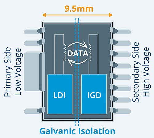 Clearance and Creepage distance: 9.5mm
Comparative Tracking Index (CTI): 600V
Distance Through the Insulation (DTI): 0.4mm
Working Isolation Voltage: 1000V
COST SAVINGS
• No further isolation barrier for driver and feedback signals needed
• Less costs for isolation barriers for other sensors
• Reduce qualification and certification efforts
• Higher quality of inverter possible
 Less components needed to get the needed peak current value
The SCALE-iDriver™ is available with 2.5A, 5A and 8A output so far. The 8A output is the highest output current for gate drivers available in the market.
Until 8A no external booster is needed. This 8A are regulated and available over the full temperature range of -40°C to 125°C ambient temperature. For turn on and turn off current two separate Pins are provided. No external diode for splitting turn on and turn off current is needed. Regarding the internal current regulation over the full temperature range even no external gate resistor is needed.
COST SAVINGS
• No need of external booster up to 8A
• No diode to separate RGon and RGoff needed
• Possibly no gate resistor is needed
Use of smaller IGBT
The SCALE-iDriver™ has an N-Channel-MOSFET output stage which leads to a very low output impedance. The output current can be higher by using the same gate resistors compared to another driver with same current rating. Measurements have shown that this can reduce the turn on (Eon) losses of an IGBT up to 70%. At the same time the turn off losses (Eoff) are still the same. Depending on the switching frequency and the design criteria for selecting the IGBT current this reduce of switching losses can lead to a smaller and so more cost efficient IGBT.
COST SAVINGS
• Use of smaller IGBT
 Integrated Overcurrent protection: Less current sensors and electronics needed
Protecting the IGBT against overcurrent is a must have of every motor drive. In most IGBT applications the usage of a gate driver with De-saturation detection (DESAT detection) protects the IGBT against high current that would lead to a destruction of the IGBT. The principle is that an IGBT desaturates at roughly four times of the nominal current. Then the IGBT is getting high impedance and the Collector – Emitter voltage (Vce) will rise up to the DC-link voltage. DESAT detection can detect this voltage and the driver will safely shut off the IGBT. Unfortunately typical DESAT detection can lead to false tripping due to forward recovery – especially in applications with dynamic loads like servo motor drives- after the so-called blanking time.
Therefore, most of the inverter manufacturers designed out the DESAT function and use other solutions like measuring the current with costly current sensors. A current sensor for every phase leg is needed, so three current sensors are required for a three phase inverter. Ideally, design should help to turn off IGBT before reach two times nominal current. This means a lot of engineering effort and also a software adaptation for every different motor drive is needed. The DESAT detection of the SCALE-iDriver™ provides a response time instead of a blanking time. Short voltage spikes are ignored and the DESAT detection can be used again for overcurrent protection also in servo motors. After a DESAT event is detected, SCALE-iDriver™ will turn off the IGBT with its patented Advanced Soft Shut Down (ASSD) function. This ASSD principle is a closed loop Gate feedback which is working without any additional external components. The short circuit event will be reported by the SO pin to primary side. By handling the overcurrent with the driver it isn’t needed to know the current of each phase. The current of the three phase system could now be measured with the Aron measuring circuit which needs only two current sensors.
 COST SAVINGS
• Using resistor chain instead of high voltage diodes
• Less effort for current sensing/signal processing
• Only two current sensors for AC current needed
• No software adaptation for different currents
OTHER BENEFITS OF SCALE-IDRIVER™
• FluxLink™ as transformer based insulation technology
• 5V CMOS input, Open Drain Failure Output
• Under voltage lockout for primary and secondary side
• Operation ambient temperature -40 to 125°C
• Maximum Case Temperature 150°C
• Design ready for 2-layers board
• UL certified (E358471)
• High Switching frequency of 250kHz
• High EMC robustness
Author: Kevin Lenz, Field Application Engineer, POWER INTEGRATIONS GmbH
If you wish to receive more information in the product, please get in touch with your CODICO contact or Mr. Ivan Mitic, Regional Sales Manager at CODICO.
Ivan Mitic
ivan.mitic@codico.com
+43 1 86 305-194
CODICO | www.codico.com | www.codico.com/shop


