


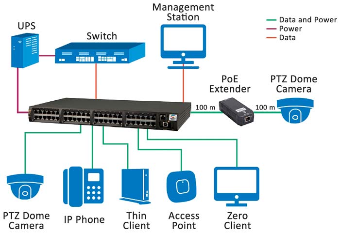
Figure 1: Midspan PoE installations are popular when upgrading an existing Ethernet system to PoE because installed cabling can be retained, and costs reduced. — (Image source: Microsemi Corp.)
A key advantage of Power over Ethernet (PoE) is its simplicity. However, the introduction of the “at” amendment to the (PoE+) to the IEEE 802.3 Ethernet standard increased the power available to powered devices (PDs) to 30 Watts (W) compared with the 15W of the original specification. For systems employing many ports, the higher capacity of PoE+ requires a large power supply to cope with demand. Moreover, systems typically include multiple power supplies for redundancy, potentially undermining PoE’s simplicity.
In a typical multiport PoE+ implementation, not all PDs will require maximum power, allowing the use of a smaller power supply. Still, the design challenge of managing different power levels from several supplies in systems that may comprise dozens of PDs remains daunting.
The solution is to base the power systems on specialized power management chips. Such chips manage power (via port controllers) to multiple PDs (with varying power requirements) from primary and backup supplies.
This article describes the basics of PoE and PoE+ before introducing single-chip power management and port controller solutions, and showing how they can ease the design of multiport PoE+ systems.
The basics of PoE and PoE+
The simplicity of PoE comes about through the combining of power and communications over a single CAT 5 cable. Using this feature, engineers can design and construct low maintenance networks quickly and inexpensively, compared to installations using separate power and data networks.
PoE gained momentum at the turn of the century when voice over Internet protocol phones (VoIP) started taking advantage of proprietary Ethernet-based technologies that allowed both data and power to be carried over the same network.
The IEEE standardized the concept by adopting a PoE specification as an amendment (“af”) to the existing IEEE 802.3 Ethernet standard in June 2003. In 2009, a second amendment, “at”, was adopted enabling PoE to safely handle higher power.
IEEE 802.3af can provide up to 15.4 watts and 44 to 57 volts DC (with a guaranteed 12.95 watts at the point of connection) to each PD on the network. Depending on the power requirement, PDs are defined as either Class 1, 2 or 3. The technology uses a single, standard RJ45 connector and CAT 5 (or CAT 3 if power requirements are modest) cable.
“Alternative B” of the standard transfers power on the two pairs of wires (of the four pairs in CAT 5 cabling) not used to transfer Ethernet data. “Alternative A” applies a common-mode voltage on the data conductors of the cable to power connected devices. Because Ethernet uses differential signaling to carry data, the applied voltage does not compromise function.
IEEE 802.3at can supply up to 30 watts (25.5 watts at the PD) and 50 to 57 volts DC to (Class 4) PDs. The PoE+ maximum current is 600 milliamps (mA) compared to the earlier technology’s 350 mA. PoE+ uses CAT 5 cable only, decreasing impedance and power losses.
The IEEE 802.3at amendment is backward compatible with IEEE 802.3af, and the latest IEEE802.3-2012 standard incorporates the 802.3at specification.
In addition to the power classes, PoE components are divided into two types:
• Type 1 which is compatible with the IEEE 802.3af specification.
• Type 2 which is compatible with both the IEEE 802.3af and 802.3at specifications.
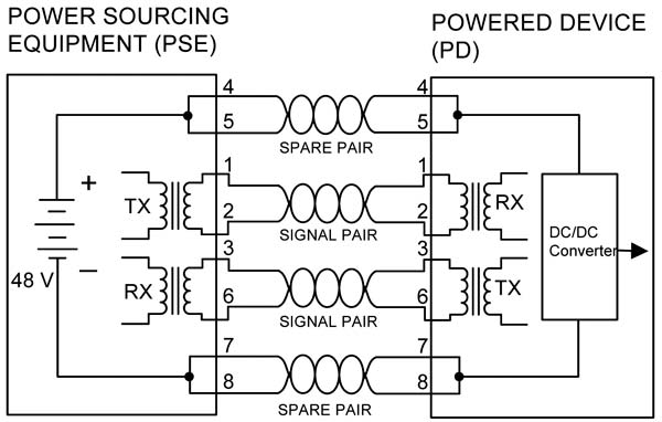
Figure 2a: PoE/PoE+ Alternative B calls for power to be delivered over spare (non-signal) pairs in the CAT 5 Ethernet cable. Midspan PoE implementations can only use this configuration. — (Image source: Silicon Labs)
The latest version of the standard prohibits carrying power over all four pairs of twisted wires in a CAT 5 cable. However, proposals for so-called 4-Pair PoE are advanced and could be added to the standard as early as this year (2018). 4-Pair PoE introduces Classes 5, 6, 7 and 8, and accommodates up to 90 watts (71 watts at the PD) and 960 mA.
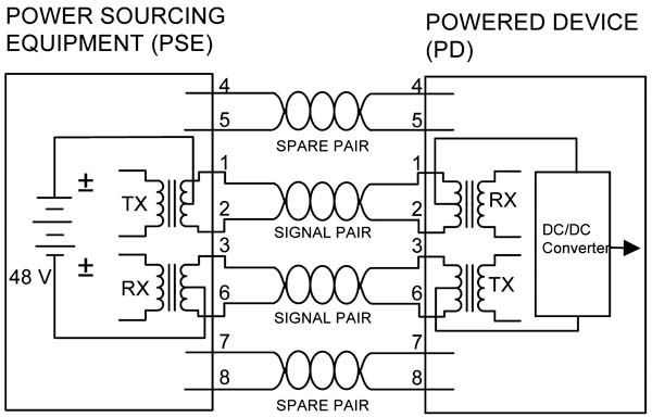
Figure 2b: PoE/PoE+ Alternative A calls for power to be delivered over signal pairs in the CAT 5 Ethernet cable. Endpoint PoE implementations can use both Alternative A and B configurations. — (Image source: Silicon Labs)
Elements of a PoE system
IEEE 802.3af defines two types of PoE device: PDs and Power Sourcing Equipment (PSE). A PSE draws power from a conventional power supply and then manages the power distributed over the Ethernet network. In turn, the PD is supplied via an RJ45 connector – eliminating the need for a built-in power supply. PoE is able to power PDs over typical Ethernet cable runs of up to tens of meters (m).
The PoE standards provide for signaling between the PSE and PD. This signaling allows conforming devices to be detected by the PSE, avoiding potential damage to non-PoE devices attached to a network. A DC voltage of between 2.8 and 10 volts is applied across the conductor, and attached PDs present a resistive load of between 19 and 27 kiloohms (kΩ) using a parallel capacitor of 120 nanoFarads (nF) or less as a “signature”. Once detected, the PSE negotiates with the PD to determine the amount of power required.
PSEs are supplied as either endpoints or midspans. Endpoints (or PoE switches) are Ethernet switches that incorporate PoE/PoE+ transmission circuitry. Midspans are PoE power ‘injectors’ sited between regular Ethernet switches and PDs, designed to add power without affecting the existing network’s signal integrity.
Endpoints are normally used on new installations or when older networks are being completely upgraded to PoE+. Midspans are employed for PoE+ network upgrades when the existing Ethernet switches are retained to lower cost and ease installation (Figure 1). An example of a midspan injector is Microsemi Corporation’s PD 9001 which is compliant with IEEE 802.3at.
There is a further important distinction between endpoint and midspan implementations; the specification only allows midspans to be used in Alternative B implementations (i.e. when power is delivered over the non-data carrying pairs in the cable) (Figure 2).
Early PSEs incorporated discrete circuitry divided into the communication interface between the power supply and Ethernet network. To simplify PoE system design, vendors then introduced integrated PSE controllers that combine the PoE+ interface circuitry with the power supply. More recently, system design has been further simplified by increasing the capability of PSE controllers such that they integrate a microcontroller to enable local supervision of multiple ports.
Practical PoE power management IC solutions
An example of a single-chip solution is Silicon Labs’ Si3459 PoE PSE port controller. The chip is designed for use in PSE endpoints and integrates eight independent ports, each with PD detection and classification functionality. In addition, the Si3459 enables PD disconnect using a DC sense algorithm, software configurable per-port current and voltage monitoring, and programmable current limits. While the chip integrates an 8051 microcontroller, a host processor is required for full control.
This processor communicates with the Si3459 via a three-wire, I2C-compatible serial interface. By using the Si3459 in a PoE system, the designer can dramatically reduce the component count and complexity of the design.
Silicon Labs supplies an evaluation kit for Si3459-based designs, the Si3459-KIT. While in normal operation the Si3459 is controlled by a host processor via the chip’s I2C interface, the kit includes a graphical user interface (GUI) making it easier to display and control the Si3459’s I2C registers. The evaluation kit requires a PC to control the evaluation board via the supplied GUI. The kit includes two Si3459 controllers supporting a 16-port demo system. Each port can supply 30 watts.
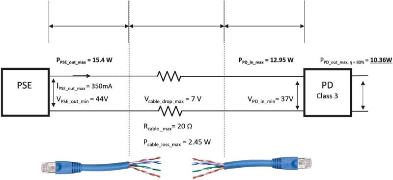
Figure 3: In this Type 1 configuration, the 20Ω cable resistance results in a power loss of 2.45 watts over the cable run. As a result, power delivered to the PD is reduced to 12.95 watts and voltage to 37 volts. — (Image source: Silicon Labs)
When calculating the power requirements for a PoE system, it is important to take into account cable losses. In a Type 1 configuration, the specification allows for a maximum cable resistance of 20Ω (Rmax) between the PSE and PD (Figure 3). Additionally, the standard defines the PSE maximum output current (IPSE_out_max), PSE minimum output voltage (VPSE_out_min), and PSE output power (PPSE_out). This configuration results in around 2.5 watts in cable losses with a corresponding lowering in power and voltage at the PD.
Configuring multiport PoE installations
The adoption of POE+ enhanced the practicality of the technology because its higher power delivery allowed a developer to connect power hungry devices such as security cameras with pan, tilt, and zoom capabilities. However, large systems with dozens of powered devices require large power supplies and complicate the design. For example, consider a system with 50 powered devices all drawing the maximum power available for a Type 2 system; the power supply would need to supply 1.5 kilowatts (50 × 30 watts). Moreover, large commercial PoE+ systems typically include backup power supplies to cover for failure of the primary unit.
However, in typical large-scale PoE+ installations, many PDs don’t require the maximum power the system can deliver. For example, devices such as Wi-Fi routers, VoIP phones, and LED lights require less than 10 watts. While this does lower the overall demand on the power supply, it does make it more difficult to configure the system’s power management.

Table 1: Cable power losses for PoE classes 0, 1, 2 and 3 (Type 1) and class 4 (Type 2). — (Image source: Silicon Labs)
Chip vendors are easing the designer’s PoE+ power management burden by offering power management controllers. These integrated devices, such as Silicon Labs’ Si3484, supervise all the power requirements of multiport PoE+ implementations.
The Si3484 is a power manager intended to supervise up to 64 ports powered by three ganged power supplies providing a single power source for the system. While the Si3484 is capable of delivering 30 W to all 64 ports, it is primarily designed to configure systems with a mix of class 0, 1, 2, and 3 devices, as well as the class 4 devices used in Type 2 installations.
The designer can configure the Si3484 power management controller via the chip’s SPI or UART interface to set the system power supply capacity, the port power configuration (Type 1 or 2), the port priority, the detection timing (which varies slightly between Alternative A and Alternative B), and the fault recovery protocol. Once programmed, the Si3484 operates without host processor intervention. Port and overall status information is available and continuously updated.
The Si3484 is designed to be used in conjunction with Si3459 PoE PSE port controller described above. The power management controller uses the real-time overload and current monitoring capability of the Si3459 to manage the power shared among 64 ports (Figure 4).
PoE power management
A single Si3484 power management controller can support up to eight Si3459 port controllers (each with eight ports) to construct an installation with 64 ports. The port controller looks after low-level port functions, such as detecting and classifying PDs, while the power management controller supervises the allocation of power across all ports.
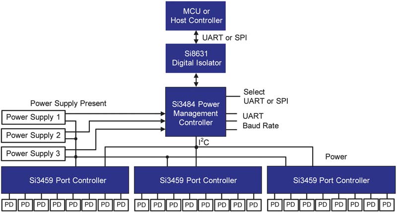
Figure 4: Silicon Labs’ Si3484 Power Management Controller works in conjunction with the company’s Si3459 Port Controller to control multiple power supplies and configure the output of multiple class 0, 1, 2, 3, and 4 ports. — (Image source: Silicon Labs)
The developer can configure an optional power limit for each port to restrict the maximum amount of power the power management controller supplies to a particular device. If a PD’s power request is greater than the limit allocated to the port, the request is denied to avoid system overload.
When additional PDs are connected to spare ports, the power management controller determines the likely power requirement from the classification of the PD. If there is sufficient overhead, power is supplied, otherwise the request is denied. The Si3484 can also dynamically adjust the amount of power granted to a PD during the course of a connection. In the event of port overload, the power management controller turns off the port.
The Si3484 chip allocates power to each port using either a grant or consumption-based policy, taking into account cable losses. Under a grant-based policy, ports are allocated a set amount of power whether it is used or not. Power for new PDs is allocated from the remaining power overhead. The benefit of this approach is that if the PD’s power consumption increases during operation, the increase can be accommodated – provided it doesn’t exceed the original grant. The downside is inefficiency because new PDs can’t access the unused allocation of existing grants (Figure 5a).
A consumption-based policy is more efficient, but could result in an overloaded port if the PD’s consumption exceeds the original allocation. To avoid repeated system overloads, the developer can specify a power reserve held back to service existing PDs if their power consumption rises above the original allocation, rather than being allocated to new devices.
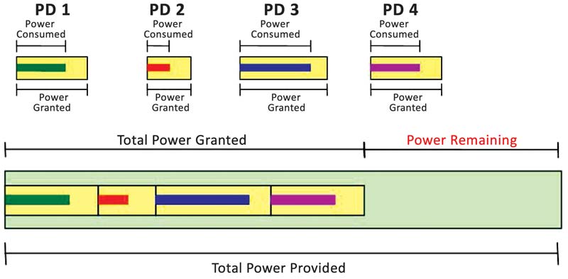
Figure 5a: The Si3484 can implement a grant-based power management policy whereby PDs are allocated a pre-set amount of power whether it is used or not. This allows flexibility of PD power consumption at the expense of system efficiency. — (Image source: Silicon Labs)
The developer can also configure the Si3484 to provide a power overload for a short duration. Such an overload is typically within the capability of modern power supplies provided it is not maintained for long periods (Figure 5b).
During operation, if the system overload is less than the overload limit, the power management controller turns off ports in priority order until the system is no longer stressed. If the system is severely overloaded (as might happen if one of the three power supplies is taken off line) the Si3484 turns off all low-priority ports and then additional ports, one at a time in priority order, until the system is safe.
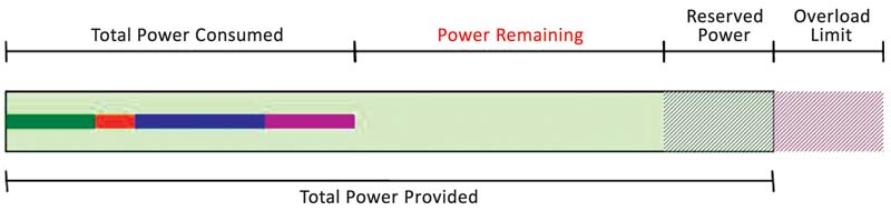
Figure 5b: A consumption-based power management policy is more efficient and enables reserve and overload power allocations. — (Image source: Silicon Labs)
Conclusion
PoE and PoE+ enable Ethernet networks to carry power in addition to data. The addition of the IEEE 802.3at amendment to the standard has extended the reach of the technology by accommodating higher power consumption devices such as moving security cameras.
However, multiple high-power ports on a large system demand large power supplies and careful power management to avoid system overload and damage. Power management controllers ease design and allow the developer to configure a multiport PoE system to precisely and efficiently meet the needs of the application.
Author: Rich Miron, Contributed By Digi-Key’s North American Editors
Digi-Key Electronics | www.digikey.com
![]()