


How to perform a simple link budget analysis to evaluate wireless transmission using sub-GHz modules in indoor and outdoor environments.
By Pradeep Shamanna, Microchip Technology
Short-range wireless is growing in popularity in home, building and industrial applications, notably in the sub-GHz (less than 1GHz) band. This means system designers need to understand the methods, estimation, cost and trade-offs involved. Apart from the range estimation formula, it is good to understand the wireless channel and propagation environment involved with sub-GHz.
Generally, RF and wireless engineers perform a link budget when starting an RF design. The link budget considers range, transmit power, receiver sensitivity, antenna gains, frequency, reliability, propagation medium (which includes the principles of physics linked to reflection, diffraction and scattering of electromagnetic waves), and environmental factors to calculate the performance of a sub-GHz RF radio link.
Sub-GHz wireless networks can be cost-effective in any low data rate system, from simple point-to-point connections to much larger mesh networks, where long range, robust radio links and extended battery life are priorities. Higher regulatory output power, reduced absorption, less spectral pollution and narrow band operation increase the transmission range. Improved signal propagation, good circuit design and lower memory usage can reduce the power consumption, thus increasing battery life.
Usually, sub-GHz channels are part of unlicensed Industrial Scientific Medical (ISM) frequency bands. Sub-GHz nodes generally target low-cost systems, with each node costing about 30 to 40% less than advanced wireless systems and they use less stack memory. Many protocols such as IEEE 802.15.4 based ZigBee (currently, the only protocol offering both 2.4GHz and sub-GHz versions in the 868 and 900MHz bands), automation protocols, cordless phones, wireless Modbus, remote keyless entry (RKE), tyre pressure monitoring systems and lots of proprietary protocols (including MiWi), occupy this band. However, operation in the sub-GHz ISM band induces the radios to interfere with other protocols using the same spectrum, which includes a threat from mobile phones, licensed cordless phones and so on.
Link budget
Link budget is the accounting of all gains and losses from the transmitter (TX) through the medium (free space) to the receiver (RX) in a wireless system. Link budget considers the parameters that decide the signal strength reaching the receiver. Factors such as antenna gain levels, radio TX power levels and receiver sensitivity figures must be determined to analyse and estimate the link budget.
Antenna types and sizes should also be considered as well as secondary factors such as required range, available bandwidth, data rates, protocols, interference and interoperability. Receiver sensitivity is not part of the link budget but the threshold is needed to decide the received signal capability.
The simple link budget equation is that the received power (dBm) is equal to the sum of the transmitted power (dBm) and gains (dB) minus the losses (dB). By assessing the link budget, it is possible to design the system to meet its requirements and functionality within the desired cost. Some losses may vary with time. For example, periods of increased bit error rate (BER) for digital systems or degraded signal to noise ratio (SNR) for analogue systems.

Test requirements
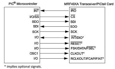
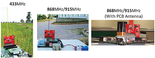
The Microchip MRF89XA modules and MRF49XA sub-GHz transceiver based PICtail boards can be used for the performance measurements. The MRF89XA modules are FCC, ETSI and IC certified. They differ from other embedded sub-GHz modules by providing various regulatory and modularly certified PCB antenna (Serpentine type) features. The PICtail boards are based on wire type (1/4) antenna for different frequencies, usually mounted on the development boards or daughter cards.
The hardware interface of the transceiver modules with any of the PIC microcontrollers, generally known as wireless nodes, is illustrated in Figs. 1 and 2. The wireless nodes can be realised with a combination of the PIC MCU development board and PICtail daughter board.
The range and performance experiments require at least two wireless nodes for testing. The measurement setup is done using any of the two development boards with, for simplicity, identical sub-GHz modules on each. Otherwise, a combination of these modules can be used for measurements and analysis, based on the application.
Measurement environment
Operating terrains highly impact the wave propagation. Range tests should be conducted in various indoor and outdoor environments to provide a basic understanding of the performance of the modules. The chosen environments included line of sight (LoS) on level and uneven terrain, and obstructed paths on level and uneven terrain.
The measurements are also based on PCB antenna orientation (vertical or horizontal), output power of the sub-GHz modules (maximum or default), power amplifier or low noise amplifier (enabled or disabled value), type of antenna (PCB, wire or standard) dipole, and antenna (Serpentine, wire, or whip and dipole).
The factors affecting indoor measurements include office equipment and whether there are any signals from Wi-Fi, Bluetooth or microwave in the vicinity. Concrete structures, walls, nearby glass, wood and metal can all have an effect.
For range tests, the main differentiating factors are the module mounting, antenna orientation and the constant battery power source.
Fig. 3 shows the vertical mounting of the antenna on the baseboard. The vertical is with elevation lobe and plane; horizontal mounting is with azimuth lobe and plane.
The antenna is mounted either vertically or horizontally based on the effective output power achieved, application space requirements and constraints, such as having a strong primary lobe based on the centre fundamental frequency and secondary lobes based on its third harmonic frequency. As radio frequencies are reduced, the antenna sizes increase proportionally. The wire length in centimetres is equal to 7500 divided by the frequency in hertz. For 433MHz, this comes to 17.3cm, and for 915MHz, it comes to 8.2cm. This equation holds good for antenna wire sizes up to a quarter of the wavelength.
Range measurement procedure
To carry out range measurements, first programme the two RF and wireless sub-GHz based transceiver nodes with MiWi P2P demonstration code. Then place one RF node on a stand on a 1.5 to 2m pole after configuring a specific operating channel. By default, the wireless node is in receiving mode.
Place a similar RF node on a second stand and set for the same working channel. Make one of the nodes stationary and the other mobile. Set up the nodes and ensure they are connected to each other. Move the mobile node and test for transmission and reception. Make the measurements every 1.5 to 3m.
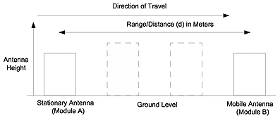
Once the critical point is attained, measure the actual and radial distance from the TX to the RX. The critical point is where the TX and RX communications become intermittent. Return about 1.5m from the critical point and check again for reliable communications. The distance measurement method is illustrated in Fig. 4 showing that the increase in range value is a function of variables with the TX module height being the most sensitive.
The packet error rate (PER) test analyses the indoor and outdoor valid data coverage between two wireless nodes. The PER test setup is similar to the open field test setup.
The PER test between two devices is done in a single iteration with a predetermined number of data packets. The ISM (IEEE 802.15.4) specification defines a reliable link as having PER below or equal to 1% for the 1000 data packets transmitted and received. PER measures the capability of a device to receive a signal without degradation due to undesirable signals at other frequencies. The desired signal’s degradation of its PER must be less than 1% or the BER must be less than 0.1%. The PER test is conducted by adding the delay between data packets, if required.
The BER measurement is done by sending the data through the wireless nodes and comparing the output to the input. Over an infinitely long period of time, the general assumption is that the data transmission is a random process. Therefore a pseudo-random data sequence is used for the BER test. It is “pseudo” random because a truly random signal cannot be created using deterministic (mathematical) methods, but few approximations of random behaviour are available to perform accurate BER measurements. The modulation modes provide good BER performance at low SNRs. However, no simple test methods exist that enable direct BER measurements.
An accepted simple method is to calculate BER from PER. The setup for measurement of the PER and BER is similar to the range measurement.
The sensitivity test setup is used to get an indication of the sensitivity limit. The input power level to the receiver is lowered through attenuators until the PER is less than 1%, and is no longer measured at the receiver. The test setup consists of two sub-GHz modules, see Fig. 5.
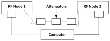
The transmitting sub-GHz module is connected through an electronic attenuator to the receiving module. Both modules are connected to a PC with a USB cable or via an RS232 serial port. The PC executes the test tool with PER test scripts using the driver utility software. All the PER tests are performed without retransmission. The PER test for sensitivity provides the user with the freedom to increase the distance between the two nodes and check how far the communications can keep PER below 1% with the compensations across channels.
Conclusion
Sub-GHz radios can create relatively simple wireless products that can operate uninterrupted on battery power alone for up to 20 years. Sub-GHz wireless networks can be cost effective in any low-data-rate system, where long range, robust radio links and extended battery life are priorities. Higher regulatory output power, reduced absorption, less spectral pollution and narrowband operation increase transmission range. Better circuit efficiency, improved signal propagation and a smaller memory footprint can result in years of battery-powered operation.
The narrowband operation of a sub-GHz radio can ensure transmission ranges as long as a kilometre or more. This allows sub-GHz nodes to communicate directly with a distant hub without hopping from node to node. The primary reasons for the sub-GHz range performance are lower attenuation rates, lesser signal weakening, and effects such as diffraction helping sub-GHz signals bend further around an obstacle, reducing the blocking effect.
It is good to use sub-GHz ISM bands for proprietary low duty cycle links and they are not as likely to interfere with each other. The less noisy spectrum indicates easier transmissions and fewer retries, which is more efficient and saves the battery power.
Both power efficiency and system range are functions of the receiver sensitivity plus the transmission frequency. The sensitivity is inversely proportional to channel bandwidth, so a narrower bandwidth creates higher receiver sensitivity and allows efficient operation at lower transmission rates. For example, at 433MHz, if the transmitter and receiver crystal errors are both 10ppm, the error is 4.33kHz for each. For the application to transmit and receive efficiently, the minimum channel bandwidth is twice the error rate, or 8kHz, whichever is ideal for narrowband applications.
For urban environments, the use of 12dB is a good rule of thumb for predicting the required increase in the link budget to double the transmission distance. Receiver sensitivity is the first variable in a system that must be optimised to increase the transmission distance. Other variables in a system also affect distance but must be changed by a greater percentage to equal the effects offered by changing the receiver sensitivity.
Fading due to multi-path can result in a signal reduction of more than 30 to 40dB, and it is highly recommended that adequate link margin is factored into the link budget to overcome this loss while designing a wireless system ■
www.microchip.com