


Exponential growth in the use of mobile data worldwide has posed significant challenges to wireless operators. Fortunately, wireless technology has continued to evolve, and Long term evolution (Lte) has become the worldwide standard of choice to meet these challenges. the top 25 worldwide wireless operators have chosen to deploy Lte, which promises better use of the operator’s spectrum by improving spectral efficiency; this means more bits per hertz than previous technologies. supporting a successful Lte transition requires a number of innovations in base station soc design.
by Zhihong Lin, Strategic marketing manager, wireless base station infrastructure, Texas Instruments and Greg Wood, Application manager, wireless base station infrastructure, Texas Instruments
As Lte deployment becomes a reality, base station manufacturers are favoring systemon-chip (soc) architectures to keep operator network costs low while maintaining and improving service. texas instruments (ti) has developed a powerful and innovative new msystem-on-a-chip (soc) architecture designed to reduce costs for Lte products and enable manufacturers to benefit from cutting-edge base station technology.
TI’s multicore SoC architecture, called KeyStone, is designed to optimize WCDMA and LTE performance while reducing base station cost and power. For wireless base station applications, an essential part of KeyStone is the implementation of configurable coprocessors for the physical layer (PHY) or Layer 1 of the wireless standards. We’ll talk more about Keystone and TI’s TMS320TCI6618 solution shortly, but first let’s review LTE with particular focus on its PHY. LTE is the latest Third Generation Partnership Project mobile standard. LTE realizes major technology advances over 3G mobile technologies and offers peak downlink rates of at least 100 Mbps and peak uplink rates of at least 50 Mbps for the 20-MHz spectrum. LTE supports flexible channel bandwidths (1.4 – 20 MHz) as well as frequency-division duplexing (FDD) and time-division duplexing (TDD) to allow flexible deployment around spectrum ownership.
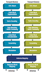
The foundation of the LTE communication protocol stack is the physical layer, sometimes referred to as Layer 1. The PHY layer is the basis of solid base station-tomobile device connectivity; without great wireless connectivity, calls drop, downloads fail, and videos stall. The PHY interfaces with Layer 2 (the media access control [MAC] layer) and Layer 3 (the radio resource control [RRC] layer) and offers data transport services to higher layers. PHY handles channel coding, PHY hybrid automatic repeat request (HARQ) processing, modulation, multi-antenna processing, and mapping of the signal to the appropriate physical time-frequency resources. LTE downlink PHY processing accepts data and control streams from the MAC layer in the form of transport blocks and begins processing by calculating the cyclic redundancy check (CRC) and attaching it to the transport block. If the transport block size is larger than the maximum allowable code block size of 6,144 bits, code block segmentation is performed. A new CRC is calculated and attached to each code block before channel encoding. Figure 1 illustrates the major functional blocks in the LTE downlink.
Turbo encoding provides a high-performance forward-error-correction scheme for reliable transmission; rate matching performs puncturing or repetition to match the rate of the available physical channel resource; and HARQ provides a robust retransmission scheme when the user fails to receive the correct data. Bit scrambling is performed after code-block concatenation to reduce the length of strings of 0s or 1s in a transmitted signal to avoid synchronization issues at the receiver before modulation.Various modulation schemes (quadrature phase shift keying [QPSK], 16 QAM [quadrature amplitude modulation], or 64QAM) are used for LTE layer mapping, and pre-coding supports multi-antenna transmission. Finally, the resource elements of orthogonal frequency-division multiplexing (OFDM) symbols are mapped to each antenna port for air transmission.
LTE Technology Evolution LTE leverages many advanced technologies used in 3G HSPA+ (high-speed packet access), like turbo coding, HARQ, and multi-antenna schemes. LTE offers a solution for 20 MHz of 100 Mbps on the downlink, 50 Mbps uplink and higher with multi-antenna signal processing schemes. TI’s TCI6618 solution supports two sectors 20 MHz, 2×2 multiple input, multiple output (MIMO) solution of 300 Mbps downlink and 150 Mbps on the uplink, with signal processing overhead for value add and advance algorithms. In addition, LTE uses OFDM and both downlink and uplink multiple-input/multiple-output (MIMO) technology to provide significant performance improvements over 3G systems. OFDM transmission – LTE uses OFDM for radio transmission, providing a robust transmission mechanism with protection against degradation from severe channel conditions, narrow-band co-channel interference, and intersymbol interference and fading. It also delivers high spectral efficiency and low sensitivity to time synchronization errors.
LTE downlink processing uses multicarrier OFDM transmission with a cyclic prefix. In the uplink, wide-band single carrier OFDM transmission with a cyclic prefix reduces the variation in the instantaneous power of the transmitted signal.
The Fast Fourier transform (FFT) provides low complexity and efficient implementation for OFDM modulation and demodulation.
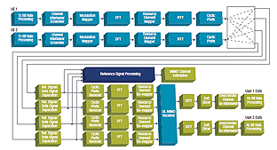
MIMO technology – Smart antenna technology using MIMO (multiple-in/multiple-out) antennas is adopted in LTE at both the transmitter and receiver to improve performance. MIMO offers significant increases in data throughput and coverage without additional bandwidth or transmit power, providing higher spectral efficiency and link reliability against fading. Figure 2 (on left) illustrates the LTE 2×4 uplink MIMO channel model and receiver handling. Multiple antenna uplink MIMO receiver techniques can help increase the signal-to-noise ratio. Maximum-ratio combining (MRC) is an effective antenna-combining strategy when the receiver is primarily impaired by noise. In interference-dominate-channel conditions, a minimum mean square error (MMSE)- combining technique is a better approach to determine the antenna weighting vector that minimizes the mean square error. Floating-point implementations of MMSE MIMO equalization can significantly reduce computational complexity and provide high performance, resulting in an efficient LTE MIMO receiver.
TCI6618 – the LTE enabler
The TCI6618 SoC is a member of TI’s TMS320C66× DSP multicore generation. Based on TI’s new KeyStone multicore architecture, it is designed for high performance wireless infrastructure applications and provides a perfect fit for LTE design challenges. Figure 3 illustrates the features and processing elements of the device. TI’s KeyStone SoC architecture provides highest throughput and future-proof architecture for LTE and its continuous technology evolution. Its multicore SoC architecture–the TCI6618 has four 1.2-GHz C66x cores that support both fixed- and floating-point arithmetic operations builds upon TI’s field-proven multicore DSP platforms and includes an innovative new floating-point architecture and coprocessors for 4G systems. Adding to the computational improvements are innovations to the backplanes and internal data movement, which are critical to achieving full performance from a high speed 4G SoC.
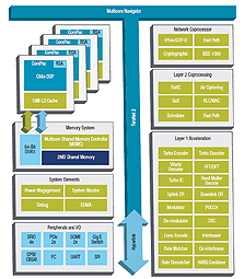
The KeyStone multicore architecture is the first to provide a high-performance structure for integrating reduced instruction set computer (RISC) and DSP cores with application-specific coprocessors and I/O. KeyStone also is the first multicore architecture that provides adequate internal bandwidth for nonblocking and zero-delay access to all processing cores, peripherals, coprocessors, and I/O. A rich set of hardware accelerators reduces the LTE system latency and frees up CPU resources to achieve optimal LTE system capacity and competitive differentiation. TI also provides LTE PHY software, offering building blocks for customer PHY solutions that are highly optimized for the C66× cores.
The TMS320TCI6618 offers the most robust hardware platform combined with a development ecosystem that includes fully optimized LTE PHY library software. What is more, platform development software accelerates development efforts to enable best-in-class LTE PHY solutions to customers.
The article has been provided by Farnell in cooperation with Texas Instruments.
For more information visit the page: www.element14.com
All products are available at www.farnell.com