


In a few years, digital power conversion has moved on from being a novelty to widespread acceptance. First to offer a commercially-available family of digitally-controlled power converters, Ericsson launched its BMR453 quarter-brick intermediate-bus converter in 2008 and followed with an eighth-brick version together with a pair of point-of-load regulators (POLs). Each of these 3E family devices introduced electrical specifications and feature sets that Ericsson believes remain best-in-class, but as with analogue-converter evolution, continuous development yields incremental benefits. The first member of a family of second-generation digitally-controlled POLs—the BMR463—poses the questions, which improvements does this 20A device implement over its predecessor, and how were they achieved?
Key metrics in power engineers’ thinking are conversion efficiency, power density, and electrical performance. Balancing these elements alongside other considerations – such as feature sets and cost – requires multiple compromises. For instance, because passive components dictate any conventional analogue converter’s loop dynamics, designers set the operational “sweet spot” at 50 – 70% of the converter’s output potential, as this is where users have previously applied such products.
By implementing a digital control architecture that adapts to line and load conditions in real time, the first-generation BMR450 extends conversion efficiency particularly under light loads, where losses predominate. The digital converter employs adaptive dead-time control for its synchronous buck converter’s switches, which safely minimises the period between the MOSFETs being off—during which time currents flow through the devices’ lossy body diodes. The strategy enhances efficiency at operational extremes and helps to flatten the efficiency curve.
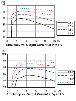
The BMR463 adds programmable strategies to optimise efficiency under light loads by minimising the effective switching frequency and preventing energy-sapping negative current flow through the lower MOSFET switch. Other new features reflect improvements to the underlying silicon together with proprietary firmware developments. Importantly, the new converter is specified for 4.5 – 14VDC input and 0.6 – 3.3VDC output levels to satisfy the wider range of conditions that today’s applications demand. Figure 1 shows performance for the conventional 12VDC intermediate-bus rail and a nominal 5 VDC input level, reflecting the trend towards lower bus voltages due to their potential for optimising system conversion efficiency.
Digital core delivers dramatic power-density and functionality improvements
Better efficiency and digital control’s greater integration permit a step-function improvement in power density, as figure 2 illustrates for the BMR450 and its analogue PMH8918L predecessor:
Apart from tripling power density, the BMR450 integrates a supervisory measurement and control subsystem that the device’s PMBus interface makes accessible—massively shrinking circuit-board complexity and area compared with any conventional analogue architecture. Board power management logic can interrogate any 3E family device to read parameters such as output voltage, current, and converter temperature, and can program the device in a running system.
The BMR463 adds a “snapshot” mode that reads key operating parameters and stores them to nonvolatile memory during normal operation, and that can be set to operate automatically under fault conditions. Designing sophisticated PMBus systems is now easier than ever and the potential benefits are huge—ranging from dynamic system optimisation that can drive down energy consumption to data acquisition that enables root-cause and predictive failure analysis.
Transient response complements basic electrical performance
The BMR463’s electrical performance is typically better than analogue converters of similar power levels. Line and load regulation remain within 3mV at any setting, while output voltage accuracy including temperature effects over the -30 to +85 degree C operating range is within ±1%. Output ripple and noise vary from 20mV peak-to-peak at 0.6V outputs to 60 mV at 3.3V and can be optimised for specific applications by adjusting the converter’s default 320kHz switching frequency from 200 – 640kHz.
In the event of a fast output current step, the digital core’s nonlinear response loop bypasses the main control loop, increasing the converter’s gain-bandwidth product to speed transient response beyond the capabilities of a linear loop. Unlike any conventional analogue POL, it is possible to fine-tune the digital loop’s default dynamic characteristics to optimise transient response performance for specific line, load, and output capacitance conditions.
Standalone and PMBus application versatility
Like all 3E family devices, the nonvolatile memory that stores the BMR463’s setup parameters can be programmed during initial manufacture or later—such as once during a host board’s ATE functional tests, or arbitrarily during system operation—to set its output voltage and other parameters via its PMBus interface. The device’s “set-&-forget” capability is useful for implementing the power-rail sequencing that multi-rail logic devices require, as well as any slew rate limiting that may be necessary to minimise power transients at system power-up. Also capable of operating in standalone mode for replacing analogue converters, the BMR463’s communications header includes pins that support remote voltage sensing, together with a pinstrap that allows one resistor to set the device’s output voltage between 0.6 – 3.3VDC in 28 increments.
At 25.65 x 13.8 x 8.2mm—0.9mm wider than the BMR450—the BMR463 adds two pins that extend its versatility. A group communications bus (GCB) pin allows multiple BMR463s to communicate autonomously. One application is to allow appropriately-configured devices to implement fault spreading, such that a temporary fault in any one converter initiates a predetermined shutdown and restart sequence that protects sensitive multi-rail chips; another is to sequence the application of voltage rails in multi-rail environments during routine power up/down events. Also simplifying multi-rail applications, an analogue voltage-tracking input complements the normal voltage sequencing so the device can track an external reference voltage and ramp its output at the same rate, or at a percentage of that rate.
The BMR463’s clock synchronisation adds the ability to shift phase angle between devices switching in up to 16 increments, reducing instantaneous loading on the input supply as current peaks are spread out across a whole switching period. The converter now includes a dedicated power-good signal that signifies when the output is within -10/+15% of its target value; these default limits are configurable.
Autonomous current sharing without OR-ing diodes
The BMR463 introduces a current-sharing mode that allows up to eight device outputs to be connected in parallel without any OR-ing diodes or MOSFETs to deliver up to 160A. This benefits systems that dynamically power down circuit blocks to minimise static power consumption, such as in response to network traffic patterns in communications systems.
When configured as a current-sharing group, the BMR463 with the lowest position within the group automatically acts as a reference that continuously broadcasts its inductor current via the GCB. Other group members assess this information and adjust their output voltages to maintain equal current delivery between each device. Some artificial droop resistance in each device’s output voltage path enables automatic compensation for inequalities such as differing circuit-board resistance paths.
Group members can autonomously set up switching phase differences between them that minimises input-rail stresses and divides the output ripple level by the number of devices in the group. In addition, a current-sharing group is able to dynamically add or shed phases in response to load conditions. This can save conversion switching energy under light loads when fewer BMR463s are necessary to service the output current demand. A group can also provide redundancy, dropping faulty phases and switching in replacements—when the group will self-configure to maintain normal operation if it can supply the necessary load current.
Footprint and packaging practicalities
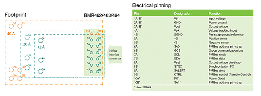
Ericsson’s designers have evolved a footprint for the BMR463 that makes provision for upcoming BMR46x devices that will extend the output current levels to include 12, 20, and 40A. Figure 3 shows this approach. Board designers can use a uniform footprint to accommodate power level changes when implementing system upgrades. Each BMR46x is available in through-hole or surface-mount versions, and designed to ease automated assembly using standard board manufacturing processes.
Please see www.ericsson.com/powermodules for application information on digital power conversion. An evaluation kit is available that provides a PC-based development environment to explore PMBus applications built around 3E family devices.
www.ericsson.com/powermodules