


A world leader in power-conversion technology required an inverter design that was flexible and easily adjustable. Standalone inverters use DC power produced from solar modules or other sources in a battery, and make it available as AC power when required. Designers must be able to connect additional inverters per phase in parallel, or for three-phase operation in applications where the user’s power requirements vary from time to time. The power must be delivered efficiently and practically and inverters must be small and portable to enable use where there is no mains power available and where emergency back-up power is essential. These types of inverters must also be easy-to-use and maintainable onsite.
by Victor Alcazar, Market Development Manager – High Performance Microcontroller Division, Microchip Technology Inc.
The customer’s inverter accepts a nominal battery voltage of 24V or 48V, weighs just 8kg and supplies a nominal output of 2200 VA at a maximum efficiency of 93%. Combining the charging technology and the inverter in a single unit achieves the goals of small size and portability. The customer used an inverter architecture based upon a high-frequency transformer, comprising an input high-frequency power stage, a high-frequency transformer, an intermediate DC link and an output-power stage. The standalone inverter relies on a small, high-frequency transformer that is unlike the bulky, heavy-duty and low-frequency transformers often deployed as an alternative.
The high-frequency concept means that the loads connected to the inverter are almost directly connected to the output stage without the attenuation often found in designs based upon low-frequency transformers. Therefore, all fluctuations on the load side can be regulated by the output-power stage. Implementing this architecture with efficiency and a high-quality sine-wave output that conformed to frequency, voltage and harmonic-distortion specifications was a major design challenge.
Connecting and switching the standalone inverters on the AC side, in parallel, together presented a subsequent challenge because a standalone inverter works as a voltage source. This means it builds up its own stable output voltage and regulates the current, depending upon the connected loads. Therefore, when two or more voltage sources are connected but are not synchronised, the loads are asymmetrical and the current flows between the sources, resulting in power losses and no active power. This current flow can also damage the power sources.
A small phase shift between two voltage sources can also cause this asymmetrical scenario, resulting in a voltage difference between them and leading to a direct connection of voltage sources on the AC side.
This occurs because of very low resistance, resulting in a very high current flow between the inverters. The customer implemented a very fast, precise, control-and-communication algorithm to address this issue.
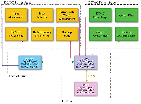
A modular design concept addressed the operational requirements of multiple standalone inverters operating in parallel. The back-up inverter works as a standard inverter (DC-to-AC) and charges batteries out of an AC source (AC-to-DC), using the same power-electronics circuitry as a generator. As there are currently no inverters available on the market that support this functionality and rely on a high-frequency transformer architecture, a brand new interface and control strategy had to be developed. Figure 1 demonstrates how the customer conceived of an inverter system comprising four different function blocks, which are served by three different signal controllers: DC-to-DC, DC-to-AC and Display and User Interface.
The customer researched available Digital Signal Controllers (DSCs) and selected dsPIC DSCs which have power supply-friendly peripherals, such as counter-based Pulse-Width-Modulation (PWM) modules, analog comparator-based feedback and coordinated Analog-to-Digital Converter (ADC) sampling, coupled with fast multiplication in a single clock cycle. These dsPIC30F DSCs can deliver the high execution rates needed for the control-loop algorithms that the customer’s inverters needed.
External components, such as a reset controller, memory chips, an ADC and a Controller Area Network (CAN) controller were not needed due to the DSCs being highly integrated. The dsPIC30F DSCs offer execution rates of up to 30 MIPS and guarantee an increase in the efficiency and reliability of the inverter system. Smooth future upgrades became another selling point as the DSCs offer support for a wide range of operating voltages from 2.5V to 5.5V.
The inverter design was flexible and modular; the DSCs offered varying densities of Flash and RAM, coupled with a variety of connectivity options. On the DC-to-DC power-stage function block, the dsPIC30F5015 DSC controls the high-frequency stage between the battery input and the high-frequency transformer. This device was also used to precisely measure the battery voltage and current. On the DC-to-AC power stage, the dsPIC30F6010A was deployed to take the power-electronics circuitry through a patent-pending Proportional Integral (PI) control loop.
For the inverter’s front panel and display controls, the dsPIC30F6010A interfaces with the dsPIC30F5011 over the CAN bus. It also adjusts the inverter’s function modes based upon the user’s commands. The dsPIC30F5011 features 66 Kbytes of Flash memory and a CAN interface and the on-chip Flash memory helps to store all graphical icons for the inverter’s multilingual user interface. Users can step through the operating modes and menus with navigation keys on the front panel.
These highly-stable inverters, with fast response times based upon high-frequency transformer technology and a modular design, have the ability to connect in parallel. Up to five additional inverters per phase can be connected in parallel in a three-phase operation, for a total of 15 inverters in a system.
The customer was able to design a compact, multi-functional inverter that enables an autonomous supply of power without the need to connect to the public electricity grid thanks to Microchip’s dsPIC30F DSCs.
www.microchip.com