Each time a new street is built the civil engineers have to think about how to illuminate the street during the night. Traditionally the lights are mains powered and therefore one had to cut roadside ditches, lay the cables and install the equipment. There is a trend starting to use solar powered lamps especially in new development areas. Currently these lights are more expensive compared to traditional lights, but due increasing energy costs they amortize pretty fast. Additionally one saves the cost of copper and construction costs as well.
by Hans-Günter Kremser, Texas Instruments
Imagine you have a road which is lit by solar powered lights and each lamp has its own light sensor in order to switch it on during night. Tolerances in the sensors and electronics parts will cause the lights to turn on at different times and not in synchronization. No mayor will approve that! In order to turn on all lights in a street at the same time they need to be synchronized, ideally without any cables.
ZigBee is a standardized protocol for Home Automation, Smart Energy and many other applications. It has some good features which one can take advantage of for this synchronization task.
Firstly it works in the license free 2.4GHz ISM band. Also the distance between the lights, typically between 40m and 60m is easily achieved with this technology. But the most important feature is the mesh capability of ZigBee. In a mesh network the information from the source node to the destination node is transported through routers. In the street light application the lights can be configured as routers.
By using the Texas Instruments ZigBee Stack it is possible to focus just on the application which is one single sensor implemented in a light and the lights which receive the sensor signal. The development of the whole application is discussed and explained in this article.
As shown in figure 1, two applications have to be developed:
1. A coordinator with the following tasks:
• Detect the light strength by a light dependant resistor
• output a PWM signal proportional to the darkness in order to control its own lamp
• send out the PWM signal so that all other lamps receive the same control signal 2. A router with the following tasks
• receive the PWM signal
• output the received signal to control the brightness of the lamp
• The same router SW can be programmed into every lamp node because we don’t need to take care about addressing, routing as all this is done by the ZigBee Stack.
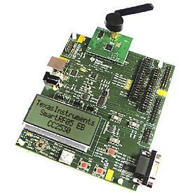
The hardware used to build up this network is available from Texas Instruments:
– SmartRF05EB Evaluation Board
– CC2530DB Daughter Board
(see picture)

The boards can be powered and programmed via a USB cable; no additional debugger HW is required.
The ZigBee Stack for the CC2530 Version 2.4.0-1.4.0 can be downloaded from the Texas Instruments web page free of charge.
The whole development has been done using the IAR Embedded Workbench for 8051 Version 7.60.1.
In order to create your own application environment it is highly recommended to read and follow the instructions in the application note “Create New Application for SmartRF05 and CC2530”, TI document number SWRA231.
In this application the “GenericApp” example which basically sends out a “Hello World” every 5 seconds, without any public profile, has been modified as described below. It should be mentioned that the GenericApp allows transmission in both ways, i.e. it is possible to send a “Hello World” message from the coordinator to the router and end-device and vice versa. The Street Light Application sends the information only in one direction, i.e. from the coordinator to the routers or end-devices.
Step 1: Light Sensor
In this application the light strength is simulated by the potentiometer on the SmartRF05 evaluation board. The integrated Analog to Digital Converter of the CC2530 is used to digitize the analog voltage from the potentiometer. By studying the schematics of the evaluation board you find out that the wiper of the potentiometer is connected to pin 12 which corresponds to port 0, pin 7 or P0.7.
This pin, like all other I/O pins, is setup as input by default. Before configuring the ADC and the timer peripheral (timer 1 will be used in this application, but any other timer, except timer 2, which is used by the ZigBee Stack as OSAL timer, can be used as well) one needs to set the output pin for the PWM correctly.
Pin 11 (Port 1, Bit 0: P1.0) is connected to an LED on the SmartRF05 EVB this is used to output the PWM signal so P1DIR should be set to 0x01. The ZigBee projects use exactly the same nomenclature as the CC2530 User’s Guide (SWRU191B) which describes all the CC2530 registers.
According the “HAL Driver API” documentation you need two function calls to read the ADC:
1. HalAdcSetReference (HAL_ADC_REF_AVDD)
This sets the reference voltage for the ADC; i.e. using AVDD as the reference means that the ADC converts 0V to zero and the max input voltage of 3V to 255 in case of an 8bit resolution and binary output.
2. HalAdcRead (HAL_ADC_CHN_AIN7, HAL_ADC_RESOLUTION_12)
This reads channel 7 which is connected to the wiper of the potentiometer and sets the resolution to 12 bits.
Care should be taken as the CC2530 ADC outputs all data in the 2s complement format, which means that our final data will go from 0 to 2047.
Both functions need the file “hal_adc.h” to be included.
The current version of the “HAL Driver API” documentation still lists a couple of Timer Services which are not valid and are not supported any more by the Z-Stack. As timer 2 is reserved by the OSAL (operating system abstraction layer), timer 1 (a 16 bit timer), timer 3 and 4 (two 8 bit timers) are free to use for the application.
Below descriptions how to configure the timer 1:
– P1.0 should be set to Peripheral function (this connects the timer 1 output to pin 12, PERCFG |= 0x40;)
– Peripheral control register should be set to “Alternative 2 location” (P1SEL |= 0x01;)
– Set Timer 1 Control register to divide the 32MHz system clock by 8 resulting 1/4MHz ticks and set the timer into Modulo mode to count from 0 to the period value set below (T1CTL = 0x06;)
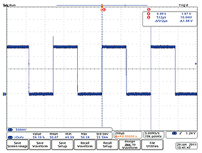
– Set the timer 1 period to 2048 (T1CC0H = 0x08; T1CC0L = 0x00;) which corresponds to a period of T = 2048 • 1/4MHz = 512µs (see picture below)

– Set timer 1 Capture/Compare Control Register Compare Mode to “Set when equal T1CC0 and clear when equal T1CC2” (T1CCTL2 = 0x34;)
These steps work to produce a PWM output on Pin 12. The duty cycle can be controlled by setting the timer 1 channel 2 capture/compare register T1CC2H and T1CC2L.
The rest should be fairly easy to achieve. After reading the analog value with HalAdcRead() you need to set the capture/compare registers accordingly.
The 12 bit value can be assigned by using the predefined macros HI_UINT8 and LO_UINT8 (T1CC2H = HI_UINT8 (read value); and T1CC2L = LO_UINT8 (read value);).
It should also be highlighted that the transmitted value needs to be a character type. Therefore the read value has to be changed from integer to character type by using the function _itoa (read value from ADC, character string, radix).
This helpful function, like many others, are also included within the Z-Stack.
Within the IAR IDE the coordinator has to be compiled and linked as ZigBee PRO Coordinator.

Step 2: Router
The router doesn’t need the ADC because it will receive the actual PWM duty cycle, directly from the coordinator. Therefore one can use the same timer settings as in the coordinator.
Following receipt of the duty cycle value you should set the capture/compare registers T1CC2H and T1CC2L accordingly. The router has to be compiled and linked as ZigBee PRO Router.
Summary:
This example project shows that it is easy to change the Z-Stack SW examples provided by Texas Instruments to the needs of the customer’s application. Following the description of how to use the A/D converter and the creation of a PWM signal most of the applications are addressed.
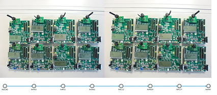
An example of a network with 7 hops (the network has been forced to join in a tree topology) is shown below:
The complete project code for the IAR Embedded Workbench can be obtained from the author.

Hans-Günter Kremser (h-kremser@ti.com) currently works as Senior Analog Field Application Engineer at Firma Texas Instruments in Munich. After his final degree in Communications in Cologne he worked in Ulm at EADS as a Development Engineer and later with two other Semiconductor Suppliers before joining TI in June 2006.


