


 The cooperation between the e-mobility specialists of Rutronik‘s Automotive Business Unit (ABU) and Vishay‘s Automotive Division realized a new reference design for a high-voltage (HV) circuit breaker with a maximum breaking capacity of 40 kW. This resettable and low-loss SiC solution with MOSFETs from ROHM replaces previous options that used mechanical relays. HV switches are an indispensable link within an HV architecture of modern Battery Electric Vehicles (BEV). They are used to safely and unambiguously separate auxiliary units from the rest of the vehicle‘s electrical architecture on the high-voltage side (400/800V side) – depending on the platform architecture – and thus prevent major damage.
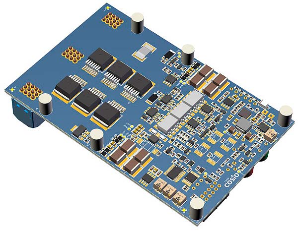
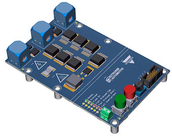
Figure 1: Illustration of PCB – 800V circuit breaker
The future of new vehicle generations is sustainable, connected and electrified!
„We are redefining the term „design service“ in distribution by developing reference products and offering services that meet the future requirements of upcoming electric vehicle platforms,“ says Uwe Rahn, Director Automotive Business Unit of Rutronik.
Next-generation electric vehicles will have up to three different voltage levels:
- A 12V electrical system for small actuators and all control units
- A 48V electrical system for larger power consumers such as water pumps, EPS or radiator fans
- A 400 to 800V electrical system containing the battery pack and the largest consumers such as the inverter, the high-voltage heater, the OBC, the HV/LV DCDC and the HVAC.
Especially the latter requires a maximum of safety and reliability for all installed components.
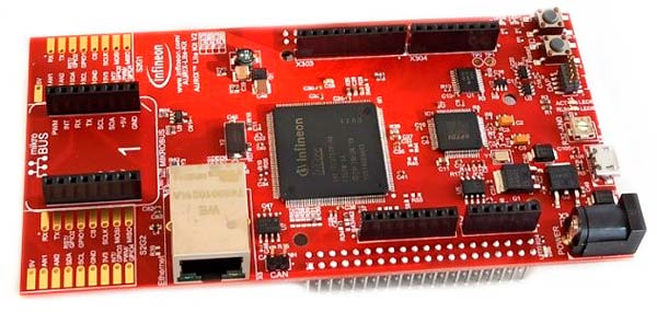
Figure 2: TC375 Lite Kit
State-of-the-art technologies for the BEV of the future
In terms of circuitry, the HV circuit breaker consists of an isolated 800V power stage with 12V measurement and evaluation electronics and an AURIX™ TC375 Lite Kit. The concept of the HV circuit breaker is realized in the switching stage with high-performance semiconductors of the latest SiC generation from ROHM, galvanic isolation of the measuring channels, high-precision shunts, new optocouplers and all protective components from Vishay. In addition, a second-generation AURIX™ microcontroller from Infineon controls the device.
Meeting highest demands with ROHM’s 1200V SiC MOSFETs
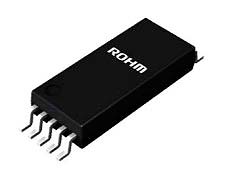
Figure 3: ROHMs SiC-MOS driver with galvanic isolation
With ROHM’s 1200V SiC MOSFETs in SMD housing and a precisely tuned control via a SiC gate driver, the HV circuit breaker is able to switch powers of up to 40kW. The resulting power loss reaches approx. 16W. The heat can be passively dissipated at room temperature (25°C). Thus, the new innovative concept exceeds the requirements of premium OEMs.
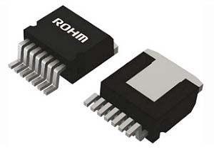
Figure 4: Rohm TO-263-7L Package
The HV circuit breaker has a pre-charge path with which capacitive loads can be pre-charged via a SiC MOSFET, pre-charge resistors and two implemented pre-charge modes (13ms or 130ms), thus preventing overcurrent at switch-on. The galvanically isolated SiC driver BM61S41RFV drives the main MOSFETs. The pre-charge MOSFET is controlled via a galvanically isolated optocoupler with phototransistor output. The maximum load current of the circuit breaker can be set either via the microcontroller or individually via a potentiometer in stand-alone mode.
High quality Vishay Products
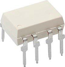
Figure 5: Linear optocoupler VOA300
The Powerstage features two high-precision shunts in parallel connection from Vishay, which are characterized by their extremely accurate bi-directional measurement of the battery current. The current and voltage measurement signals are transmitted galvanically isolated (floating measurement), processed by measurement signal amplifiers and passed on to the microcontroller. The newly developed VOA300 linear optocouplers from Vishay provide galvanic isolation to the 12V side. The previously mentioned optocoupler with phototransistor output driving the pre-charge MOSFET is Vishay’s VOMA617A.
Eight high-voltage MLCCs from Vishay of which two are series-connected each, provide the galvanically isolated supply of the op-amps, the SiC-driver and optocouplers. This supply includes a push-pull driver stage with 50 kHz. The AURIX™ board is connected via a cable connection and, after successful connection, can output the measured and processed values via an already implemented software. The configuration and readout of measured values of the eFuse with AURIX™ control is done via an existing CAN interface.
Precise measurements, diagnostic function and protective measures
In addition to the precise current and voltage measurements, the concept also has a diagnostic function and further protective measures, such as over-current detection with adjustable threshold, in- & output transient protection as well as additional TVS diodes for power supply protection. The input and output voltage is monitored via ratio metric thresholds, which thus also enables use for 400V systems. To reduce voltage fluctuations due to a high driver output current the main SiC driver is buffered via a new polymer tantalum capacitor (T51 series from Vishay). In addition, the reference design has a status display with LEDs as well as two push buttons for manual control. Equipped with a housing that allows access to all measuring points, protection against accidental contact is also guaranteed.
For the highest demands and optimised time-to-market
Rutronik makes the innovative reference design available to selected customers with above-average requirements, thus enabling fast and high-quality implementation of a state-of-the-art circuit concept in future projects.