


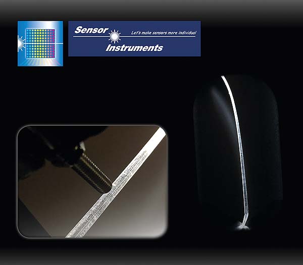
The color sensor determines the local intensity and color of the light guide rod.
Light Guide Rods
More and more cars today are equipped with light guide rods in their interior, the so-called ambiance area, for example in door panels, dashboard, center console, and roof lining. Through semi-transparent flat strips these light guide rods guide the light into the interior of the car.
Any inhomogeneity in the light guide rod would influence the scattering behaviour of the output light. When driving in the dark, a passenger in the car interior would notice this as a bright or dark position along the light strip and would be disturbed by it.
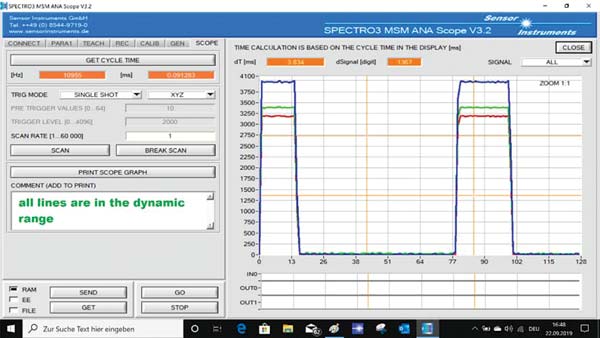
All averaged RGB signals are in the dynamic range (displayed by SAT black), because all non-averaged RGB signals are within the dynamic range.
Inhomogeneities in the radiation behaviour are caused by so-called hotspots, i.e. refraction index discontinuities in the transparent plastic of the light guide rod.
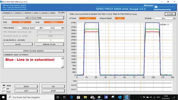
Blue – Line is in stauration
Both the local intensity and the color of the light guide rod can be determined with the color sensor SPECTRO-3-FIO-ANA-LEDCON-HA.
The fibre-optics frontend is moved along the light guide rod for example by means of a robot. Flaws or hotspots are picked up by the sensor as a weak or intensive signal because they have too little or too much light.
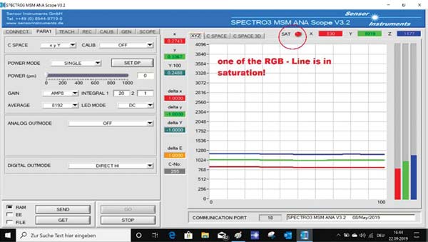
The averaged RGB signals seem to lie in the dynamic range, whereas at least one non-averaged RGB signal already is in saturation (indicated by SAT red).
Due to the so-called pulse width modulation of RGB LEDs, placed at one of the front sides of the light guide rod, there may be considerable intensity peaks of the light pulses. For example the blue LED only is in active mode for approx. 10% of the cycle time. Since the color sensor usually (with corresponding parameterisation) provides the average intensity value (with correspondingly long averaging, in a way as seen with the human eye), it must be checked during averaging whether the respective signal (R, G, B signal) still lies within the permitted dynamic range.
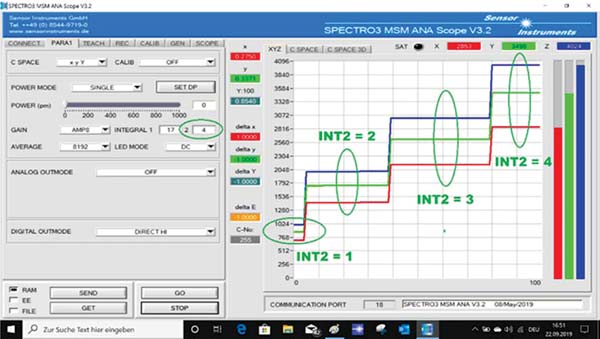
With INT2 the averaged signal can now be amplified.
If the signal leaves the operating range, a corresponding information is sent through the digital-serial interface of the color sensor. With INT1 and INT2 (software amplification before and after averaging) the received, averaged, and evaluated signal level can be optimally adjusted. In parallel to this it also is ensured that the non-averaged signal still remains in the specified dynamic range.
www.oboyle.ro