


Many modern electronic systems rely on accurate timing in applications such as telecommunications base stations (both fixed as well as mobile) and ground based and airborne based radar stations. Such applications require not only highly stable frequencies but also a very low phase noise performance.
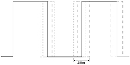
The definition of stability is fairly self-explanatory being the shift of frequency over the operating temperature range. For example ±50ppm over -40 to +85C in the case of a clock oscillator or ±50ppb in the case of an OCXO (Oven Controlled Crystal Oscillator). The phase noise performance (from which the jitter performance can be defined) is the short term variation or fluctuation of the oscillator frequency within the frequency domain. (See figure 1)
Effectively the lower the phase noise figure the higher the performance of the oscillator. For example a figure of -170dBc/Hz at 10kHz offset is a worse measurement than -175dBc/Hz at 10kHz offset.
In terms of oscillator performance generally the performance is defined by the families in which they are located and start with Clock Oscillators (SPXOs), Voltage Controlled Crystal Oscillators (VCXOs), through Temperature Compensated Crystal Oscillators (TCXOs) and then onto Oven Controlled Crystal Oscillators (OCXOs) which are the best in terms of overall performance including phase noise. We shall now look at some aspects of OCXO design considerations which are particularly important when it comes down to achieving a low phase noise performance.
The basic design of the OCXO can be broken down into a number of building blocks (see figure 2).
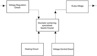
We shall therefore look at each of these blocks in sequence and give some idea of their effect on the phase noise performance of the oscillator. As is to be expected the most important component within the OCXO is of course the crystal.
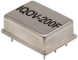
Generally speaking, the crystal has the most effect close into the carrier that is up to an offset of 10kHz. To take as an example IQD’s recently released IQOV-200F series (see figure 3) of OCXO this has typical phase noise figures at a nominal operating frequency of 100MHz of -95dBc/Hz at 10Hz offset, -130dBc/Hz at 100Hz and -175dBc/Hz at 10kHz offset. These figures are achieved by the use of a 5th Overtone 100MHz crystal housed in a HC43 style holder. As is now usual in very high specification oscillators an SC-cut crystal (stress compensated) is used with a turnover temperature of around 87 degrees C. Normally the crystal will be held under vacuum which has the effect of improving the long term ageing performance of the unit, and as we shall see later on in this article the exact turnover temperature of each individual crystal is catered for at the alignment stage. It should be noted that by their very nature SC-cut crystals are relatively thin in profile (only a few microns) and therefore need very careful handling prior to being encapsulated since they are very easy to break.
The method of mounting the crystal within the enclosure also needs to be considered by the manufacturer since its mechanical movement can also have an adverse effect on phase noise performance. Do you for example choose a two point mount or a four point? Do you use a flexible or a non-flexible adhesive to hold the crystal in place? These are all things that the manufacturer needs to consider and most often need to be thought about whilst taking into consideration the customer’s application.
It is well worth emphasising time and again that high performance OCXO’s are most often a key component within a customer’s system so it is useful to establish a good working relationship with the manufacturer you intend to use in order for you to both understand which parameters need the most careful consideration in the design and which do not. It helps to get the best performance out of your product after all!
It is also helpful to use an oscillator manufacturer who designs and manufacturers their own crystal units since then of course the crystal and its drive circuitry can be closely matched for optimum performance.
It is important that all frequency dependant components are located as close as physically possible to the crystal and its heating element in order to maintain a tight frequency stability and phase noise performance. This will of course include the tuning capacitors and any overtone selection circuit. It is also important to ensure that the holder of the crystal is bonded to the actual substrate or printed circuit board used so that the thermal management of the device is tightly controlled. This can be achieved by the use of a thermally conductive adhesive.
In respect of the heating element this will normally comprise an operational amplifier driving a power transistor. The input to the amplifier consists of a selective thermistor/ resistor network, the values of which are chosen individually so that the precise turnover temperature of each crystal is set. The power transistor should be located as close as possible to the crystal and located in such a way as to minimise any temperature gradients across the crystal since this will give rise to poor stability and phase noise if it is not so. This part of the circuit can, as intimated earlier be used to set the individual turnover temperature of the particular crystal employed. Very simply every crystal has to be matched to the drive circuit so as a consequence there is a series of “set up” procedures involved in every device. This of course takes some time to enact since the oscillator has to be allowed a finite time in order to stabilize its frequency.
The circuit of the supply used to provide the power to all aspects of the oscillator must of course use low noise components (as of course must the rest of the circuit) in order to achieve optimal phase noise performance.
It is sensible to use a voltage regulator with a low drop out and one that you can adjust in order to make maximum use of the input voltage available. In effect by driving the oscillator part of the circuit as hard as possible you can keep help to maximise the phase noise performance. This regulation part of the circuit should, in the best designs be followed by a filter circuit in order again, to minimise the potential for noise to find its way through to the more sensitive parts of the circuit i.e. that of the oscillator circuit itself! It goes without saying that in order to achieve maximum performance from the packaged oscillator the input voltage supplied must ideally be as clean and as regulated as possible. That effectively means as stable as possible and with as minimal a voltage ripple as can be achieved.
In terms of the output the best possible output design to go for from a low phase noise perspective is for a high power Sine wave output into 50 Ohms.
This of course provides for a much cleaner output than say a HCMOS logic output which, by its very nature inherently has many harmonics and therefore much “noise” contained within it.
The final aspect of the circuit within the OCXO to be considered is the voltage adjustment circuitry. This is to allow for the frequency shift of primarily, the crystal over time. We mentioned earlier that the crystal unit is sealed under vacuum during the course of its manufacture. It is most important that extreme care is taken during the process of its manufacture since contamination is its most problematic aspect. This is of course mainly contamination from the atmosphere where it can deposit itself on the crystal blank and affect the actual frequency of oscillation. Since it adds an extra mass which slows the frequency down. Poor construction can also have an effect since any material left within the crystal can which should not be present will have a similar degrading effect.
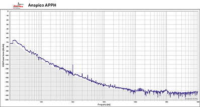
A typical phase noise performance plot achievable from a high performance modern OCXO design is shown in figure 4. This level of performance illustrates again the need for a close relationship between manufacturer and customer.
No matter how much care is taken during the course of the manufacture of the crystal there will always be an element of “ageing”. In order to minimise the effect, a quality oscillator manufacturer will always carry out an element of pre-aging on the crystal prior to its fitment within the oscillator. This will often involve an element of “passive ageing” whereby the crystal is stored at an elevated temperature (say 85 degrees C or 105 degrees C) during the course of its construction. It may also involve, powering the crystal up with an oscillator circuit before fitting into the final OCXO since active ageing is always preferable to passive but anything is better than nothing!
Once the crystal has been fitted to the final oscillator and the unit fully aligned and tested it will normally be placed in an ageing rack for a period of say 30 days during which time its ageing or frequency performance is monitored probably on an hourly basis. This information will enable the manufacturer to predict its performance over a period of many years, it also enables the manufacturer to weed out any devices that have an early life mortality rate which is not normally a big issue.
In the past, frequency adjustment was normally carried out by mechanical means that is by an internal capacitive or resistive trimmer accessible through an access hole in the can. This has the detrimental effect that the external enclosure is not able to be hermetically sealed. The usual method of frequency adjustment these days is by electronic means, that is by the use of applying an external voltage through a least one Varactor diode. It is more usual, however to use two Varactors in order to achieve a high level of linearity. Care must again be taken in their selection since a lot of these devices are very “noisy” and can therefore have detrimental effect on the ultimate high phase noise performance we are looking to achieve.
Finally, consideration should be given to the insulation used within the enclosure although as with the crystal element, the device itself is backfilled with dry nitrogen during hermetically sealing it does appear that the use of an internal insulation blanket can have a positive influence on improving the phase noise performance of the oscillator, although there is a lot more investigative work to be carried out in order to confirm this!
As can be appreciated the design of a high end OCXO is very involved and consideration has to be given to many factors, all of which are interlinked when it comes to looking to achieve the minimum possible levels of phase noise from the oscillator. The end result of course, represents many years of research and development into achieving the best possible performance in order to meet with the customer’s requirement.
www.iqdfrequencyproducts.com