


When I first began working with fluid dynamics, I was advised the field was as much an art as a science. Working to improve the efficiency of industrial pollution control equipment through better flow distribution, we studied field test data, developed solutions, built scaled models to test them, and then often held our breath when it came time to see if they scaled up properly. Fluid dynamic calculations often take on assumptions of idealized conditions, when the actual case may be far from it. Even after running highly complex computer modelling, engineers frequently find themselves making final design adjustments to designs in their laboratory.
by Donna Sandfox, Product Manager, Omron Electronic Components LLC
The behaviour of gas flow and achieving a stable, accurate mass flow measurement is affected by many factors. The composition of the gas will affect properties such as density and thermal conductivity.
Environmental conditions like temperature, humidity and altitude play a part, as does the medium through which the flow is moving.
The surface roughness of the tube/Mass flow sensors are often preferred to volumetric sensors, as volume is dependent on pressure and temperature, while the mass can be thought of as “how much” (not to imply that mass flow sensors are completely immune to these changes, particularly temperature).
Going back to basic thermodynamics is the Ideal Gas Law (PV=nRT) – a prime example of a formula assuming idealized conditions; at least this one advertises itself as such.
A quick refresher…
Pressure × Volume = Amount of Gas (moles) × Universal Gas Constant × Absolute Temperature
Moles = Mass / Molar Mass. Molar mass is a gas- specific constant.
Rearranging and combining constants, Volume = Mass × Temperature/Pressure × Constant
Why are “mass flow” sensors then rated in LPM (Liters per Minute)? If you examine the datasheets closely, you should find that the LPM readings are at a stated set of “standard” or “normalized” pressure and temperature conditions. These standards will vary depending on which organization was referenced (NIST, IUPAC…). 1 atm and 0°C are commonly used. pipe/duct influences the resistance between the gas and the walls.
Selecting a mass flow sensor that is suitable to the application can be a challenge, and mistakes can be costly. In the paragraphs that follow, I will illustrate a number of factors of which to be mindful. Some will be relevant to a variety of sensor types; others will focus on thermal based mass flow sensors.
Gas Composition
When selecting a flow sensor, the first thing we think about is the appropriate flow range. Make sure to check which gas type the sensor is calibrated for, as gas composition will change the output of many sensors. Air is the most common, but not always the case. When using a different gas, always contact the sensor manufacturer. Text book conversions don’t necessarily apply across the board for different sensor types. Gas density is certainly a factor, but for temperature based mass flow sensors, thermal conductivity is also quite important. Omron, for instance, will provide alternate output curves for some gases (air vs. natural gas vs. argon), but recommends a custom factory calibration to achieve optimal results for other gases (ex: carbon dioxide and nitrogen oxides). If the gas composition will be changing significantly, look for a sensor that is designed specifically for that condition, as most cannot distinguish the difference between a change in density versus the amount of flow.
Turbulence and Pulsation in the Gas Stream
Turbulence and/or pulsation in the gas stream can result in unstable and inaccurate flow measurement. These issues can be addressed in the design of the flow path around the sensor, however, some sensors are designed to be more tolerant of these conditions.
Several of Omron’s in line sensors are designed with a series of inlet screens (see
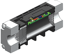
Figure 1) which act to smooth out turbulent flow and provide a very even flow across the diameter of the sensor. This results in a representative velocity moving over the MEMS chip. When using a sensor without a laminar flow structure, incorporating sections of straight pipe upstream and downstream of the sensor is often recommended. The required length of this section can be calculated by using the Reynolds number, however, some suggest approx 10 diameters upstream and 5 diameters downstream.
Additionally, when screens are not used, some manufacturers recommend a filter upstream of the sensor to protect the sensing element in particulate laden environments.
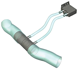
Pulsating flows, such as those from diaphragm pumps, can be addressed by a few methods. Outside of the sensor, a buffer tank upstream of the measurement device or an orifice down stream are two options. Within the sensor design, an orifice installed within the sensor (ex. Omron’s 70 200 LPM D6F 01/02A2 model) may be sufficient. Flow sensors which incorporate an internal bypass design have also shown to be less prone to pulsation issues. An internal bypass is where a small amount of flow is pulled from the main flow path over the sensing element, rather than the sensing element being located in the main flow path of the sensor (watch for Omron’s D6F AB type to be released soon). A similar solution is to use a smaller sensor in a bypass (see Figure 2). More details on this type of set up are discussed below.
The pulsation phenomenon is difficult to model. Sometimes trial and error is the only way to determine the best approach for a particular system. In exceptionally difficult situations, a combination of the above methods are sometimes required.
Sensor Characteristics
It is also important to make sure the characteristics of the sensor are compatible with the application. The response time of the sensor is critical in a number of devices, and this characteristic can vary significantly. Some manufacturers will modify their timing constant upon request. Please note that a faster response time may result in more noise in the output signal.
Some applications have a limit to the pressure drop they can tolerate (ex. breathing circuits in medical devices). A sensor with minimal internal restrictions, or using a small sensor in a bypass configuration (see Figure 2) are two options.
Bypass Set up
The bypass set up involves more design work, however, a smaller and often less expensive sensor can then be used. (Omron’s factory engineers offer design assistance utilizing Computational Fluid Dynamics modeling software for customers interested in this option.)
Flow sensors in a “bypass configuration” are similar to using a differential pressure sensor (an indirect flow measurement method); however, there are some technological differences that should not be overlooked. In both instances, the sensor is connected to two ports, which are installed on either side of an orifice creating a pressure drop.
In differential pressure sensing, the difference in up-stream and downstream pressures is measured on either side of a diaphragm. It’s a static system — the air does not pass through the diaphragm.
A mass flow sensor is a dynamic system, as the airflow continually passes through the sensor. The major implication of this difference is that the pressure drop of the “bypass system” will influence the output of some sensors, meaning that the tube lengths of the bypass need to be controlled in the manufacturing process. In many applications this is not an issue; however, it can be in those such as HVAC control where tubes are installed in the field.
This problem can be avoided by the use of High Impedance Flow Sensors which have a very narrow, high velocity flow path.
While I’m sure I haven’t addressed all the potential issues to consider when selecting a flow sensor, I hope I’ve helped in the avoidance of some common pitfalls. If fluid dynamics is not your area of expertise, don’t be afraid to ask for some assistance at www.element14.com