


 Introduction
This article about Automotive Audio Bus® (A2B®) technology explains recent advances in digital microphone and connectivity technologies. These innovations are enabling swift adoption of game-changing applications for future generations of vehicle infotainment systems.
Markets and Application Landscape
Within the automotive in-cabin electronics segment, it’s becoming increasingly clear that the universe of audio-, voice-, and acoustics-related applications is rapidly expanding as car manufacturers attempt to differentiate their vehicles from the competition. Additionally, as average consumers become more tech savvy, their expectations related to both the driving experience and level of personal interaction with the vehicle are expanding significantly. Home theater quality sound systems are commonplace across all vehicle price points and are now being augmented by sophisticated hands-free (HF) and in-car communications (ICC) systems. Additionally, active and road noise cancellation (ANC/RNC) systems, historically deployed in only the top-level premium vehicles, are now making their way into more mainstream, affordable segments. Looking to the future, audible or acoustics-based techniques will become a critical component in Level 4/Level 5 autonomous vehicle engine control units (ECUs) as they attempt to detect the presence of emergency vehicles.
The common thread binding all these legacy and emerging applications is the dependency on high performance acoustic sensing technology such as micro- phones and accelerometers. And since nearly all emerging applications require multiple acoustic sensors like microphones (or mic arrays) to achieve the best system-level performance, a simple cost-effective interconnect technology is required to ensure that total system costs are minimized. Historically, the lack of a microphone-optimized interconnect technology has been a significant pain point for car manufacturers, as each microphone would need to be directly connected to the processing unit using expensive and heavy shielded analog cable. These added costs—primarily in terms of actual wiring, but secondarily in terms of added weight and reduced fuel efficiency—have in many cases prevented the widespread adoption of these applications, or at least limited them to only the super-premium segments. Recent advances in both digital microphone and connectivity technologies are proving to be enablers to the swift adoption of game- changing applications in future generations of vehicle infotainment systems. A2B technology will make a difference.
Traditional Analog Microphone Implementations and Limitations
Using a handheld cell phone while operating a vehicle is banned in most countries, while Bluetooth®-enabled hands-free devices have become standard equipment in almost all vehicles. A wide array of hands-free solutions is available, from simple standalone units containing a loudspeaker and microphone to advanced solutions that are completely integrated within the vehicle infotainment system. Until recently, most hands-free systems were implemented in a very similar fashion. They were comprised of only one (rarely two) microphone(s), and the associated microphone technology was the 50-year-old electret condenser microphone (ECM) type. The voice quality of the transmitted audio was often unsatisfactory, especially in simple standalone units where the distance between the microphone and the talker’s mouth could be rather large. Communication quality could be improved if the microphone were mounted as close to the mouth as possible (for example, in the headliner of the vehicle). However, in this case, both front seats require individual microphones if the driver and passenger are to be equally supported.
A typical automotive ECM is a device that combines the ECM capsule with a small amplifier circuit in a single housing. The amplifier delivers an analog signal with a voltage level that allows transport over wires of several meters in length, as required in typical automotive installations. Without amplification, the original ECM signal would be too low for such a wire length, as the signal-to-noise ratio (SNR) would degrade too far due to electromagnetic interferences on the wire. Even the amplified signal requires shielded wiring, which is typically a 2-wire cable with a bias (8 V) that supplies the microphone device. Given such wiring requirements, it is obvious that the number of ECM devices used in mainstream vehicles is limited due to weight and system cost constraints.
One of the few advantages of ECMs is their built-in acoustic directionality, which is usually trimmed to a super- or hypercardioid polar pattern (a MEMS mic can also be made unidirectional but typically requires more complex acoustic designs). Typically, 10 dB or more backward attenuation can be achieved, where “backward” means the direction toward the windshield, from which only noise (that is, no desired signals, such as the talker’s voice) originates. Having a higher sensitivity in the incoming direction of the desired signal is very beneficial to increase the SNR. However, directional ECM capsules introduce unwanted side effects such as the high-pass characteristic where sensitivity decreases at lower frequencies. The 3 dB cutoff frequency of such a high-pass response is typically in the range of 300 Hz to 350 Hz. In the early days of HF technology, this high-pass behavior was an advantage because engine noise was present primarily at lower frequencies, so the engine sound was already attenuated through the microphone. However, since wideband, or HD, telephony is available, this high-pass behavior starts to become a problem. In a wideband call, the effective bandwidth is increased from 300 Hz to 3400 Hz, to 100 Hz to 7000 Hz. The built-in high-pass filter of the microphone makes it necessary to amplify signals between 100 Hz and 300 Hz in the postprocessing unit, which would not be required if the microphone were to deliver better audio bandwidth in the first place. Another disadvantage of ECM technology is the significant part-to-part variation in terms of sensitivity and frequency response. The relatively large manufacturing tolerance of ECMs may not present a problem for single microphone applications. However, if more than one microphone signal is deployed in a small-spaced microphone array application, then tight matching between microphones is essential for optimal array performance. In such a case, ECMs can hardly be used. Furthermore, from the physical size perspective, traditional ECM capsules are not generally suitable for small form factor microphone arrays.
Microphone arrays have experienced widespread applicability including in vehicles because they can provide similar, often superior, directionality performance when compared to traditional ECMs. Spatial information regarding sound impact directions can be extracted from the microphone signals using two or more suitable microphones grouped in an array. This class of algorithms is often referred to as beamforming (BF). The name beamforming is borrowed from an analogy with phased array antenna technology, where a radio “beam” is formed from the emission of an antenna array focused in a certain direction using a simple, purely linear filter and sum algorithm. Although there is no such beam in a microphone array, the term beamforming has also become very common in the field of microphone signal processing, where it covers a much wider range of both linear and nonlinear algorithms that enable higher performance and greater flexibility than the simple linear beamforming process.
In addition to the BF processing, a raw microphone signal almost always requires postprocessing because every HF microphone captures both desired voice signals and disturbances in the environment such as a car cabin. Wind, road, and engine noise deteriorate the SNR, and signals being played by loudspeakers—usually referred to as loudspeaker echoes—are additional sources of unwanted signals. In order to reduce such disturbances and improve voice quality, elaborate digital signal processing techniques are required, often referred to as acoustic echo can- celling and noise reduction (AEC/NR). AEC removes the loudspeaker sound from the microphone, which otherwise would be transmitted as an echo of the voice of the person speaking at the other end of the line. NR reduces constant driving noise while increasing the SNR of the transmitted signal. Although elaborate specifications (for example, ITU-T P.1100 and P.1110) that define many performance details of an HF system have been published by the International Telecommunication Union (ITU), the subjective impression of the communication quality in a call from an operating vehicle can be unsatisfactory if the AEC/NR processing is of substandard quality. Together with the previously mentioned BF algorithm, the bundle of AEC/NR/BF enables a wide array of new applications, all related with some level of digital audio signal processing. To support these applications, a new generation of microphone technology overcoming disadvantages of traditional ECMs is demanded.
Digital MEMS Microphones—Technical and Performance Advantages
Microelectromechanical systems (MEMS) technology is swiftly becoming the new industry standard for microphones, as it offers many advantages over traditional ECMs. First and foremost, MEMS enable a much smaller form factor sound sensor than existing ECM capsules. Additionally, integrating a MEMS sensor with an analog-to-digital converter (ADC) in a single IC results in a digital microphone that delivers signals ready for AEC/NR/BF processing.
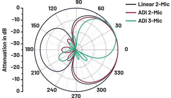
Figure 1. Polar attenuation characteristic of different BF algorithms. — © ADI
Analog-ported MEMS microphones without an integrated ADC are also available, but they share many of the same disadvantages as analog ECMs and even require more complex amplifier circuitry than ECMs if operated on the traditional 2-wire analog interface. It is only with an all-digital interface technology that the interference and SNR problems inherent to analog wires can be significantly alleviated. Also, from a production perspective, MEMS are preferred because MEMS mics can be produced with a much tighter specification variance than ECM capsules, which is important for BF algorithms. Lastly, with MEMS IC microphones, the manufacturing process is greatly simplified because automated mounting techniques can be utilized, which reduces overall production costs. From an application perspective, the smaller form factor is the largest advantage, and, due to very small sound-entry portholes, MEMS mic arrays can be made virtually invisible. The porthole and the sound channel to the sensor require great care in terms of design and production quality. If the acoustic seal is not tight, noise from the inner structure may reach the sensor and leakage between two sensors may degrade the performance of the BF algorithm. Different from typical ECM capsules that can be designed and manufactured to be either omnidirectional or directional, MEMS microphone elements are almost always manufactured to be omnidirectional (that is, they have no intrinsic directionality of sound reception). As such, MEMS microphones are phase-true omnidirectional sound pressure sensors that deliver ideal signals for advanced BF algorithms, where attenuation directions and beam widths can be user-configurable via software.
As a rule, it is very important that all signal processing modules are grouped in an integrated algorithm suite. Processing latencies would needlessly increase, and overall system performance would be degraded if functional blocks were implemented in isolation from one another. For example, a BF algorithm should always be implemented together with the AEC and, optimally, from the same provider. If the BF algorithm introduces any nonlinear effects on the signal, the AEC will most certainly produce unsatisfactory results. Ideal results of digital signal processing can best be achieved by an integrated algorithm bundle that receives uncorrupted microphone signals.
Standard linear BF and ADI-proprietary algorithms are compared below in detail in order to fully understand the performance potential of advanced BF algorithms. The plots in Figure 1 show three different BF algorithms regarding polar characteristics and frequency response in both in-beam and off-beam directions. A standard linear supercardioid algorithm based on a 2-mic array serves as the benchmark (black curves). The benchmark curve shows the maximum attenuation in the typical zero-angle directions (that is, maximum off-beam attenuation) and a “rear-lobe” at 180°, where off-beam attenuation is lower. The resultant rear-lobe is a trade-off with beam width in a linear algorithm. A cardioid beam (not shown) has its maximum attenuation exactly at 180°; however, its receptive area is broader than a hyper- or supercardioid configuration. Beams with less significant rear-lobes and higher off-beam attenuation can be achieved with nonlinear algorithmic approaches, with the red curve showing an ADI-proprietary 2-mic algorithm of this class (microphone spacing: 20 mm).
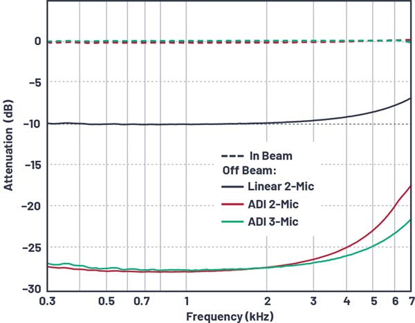
Figure 2. In-beam (dashed lines) and off-beam (bold lines) frequency responses of different BF algorithms. — © ADI
With two omnidirectional microphones in an array, there is always a rotational symmetry of the beam shape. In other words, the attenuation at X° in the polar plot is the same as at 360° – X°. This assumes that the 0° to 180° line of the polar plot is equivalent to the imaginary line connecting the two microphones. The 3-dimensional beam shape can be imagined by rotating the 2D polar plot around this microphone axis. Asymmetric beam shapes without rotational symmetry or more narrow beams require at least three microphones arranged in a triangle. For example, in a typical overhead console installation, a 2-mic array can attenuate sound from the windshield. However, in such an orientation, a 2-mic array cannot distinguish driver from passenger. Rotating the array by 90° would make such driver/passenger distinction possible, but the noise from the windshield would not be distinguishable from sounds inside the cabin. Both windshield noise attenuation and driver/passenger differentiation are only possible using three or more omnidirectional microphones configured in an array. An exemplary polar characteristic of a respective ADI-proprietary 3-mic algorithm is given by the green curve in Figure 1 where the microphones are arranged in an equal- sided triangle with 20 mm spacing.
Polar plots are computed with band-limited white noise arriving at the microphone array from different angles. The audio bandwidth is limited to 100 Hz to 7000 Hz, which is the wideband (or HD-voice) bandwidth of state-of-the art cell phone networks. Figure 2 compares the frequency response curves of the different algorithm types. In the in-beam direction, the frequency response of all algorithms is, as expected, flat within the desired audio bandwidth. The off-beam frequency responses are computed for the off-beam half-space (90° through 270°), confirming high off-beam attenuation over a wide frequency range.
The relationship between array microphone spacing and audio bandwidth vs. sample rate is worth further discussion. Wideband HD-voice uses a sample rate of 16 kHz, which is a good choice for speech transmission. There is a huge difference in voice quality and speech intelligibility between the current 16 kHz wideband sample rate and 8 kHz, which was used in earlier generations of narrow-band systems. Driven by speech recognition providers, there is growing demand for even higher sample rates, such as 24 kHz or 32 kHz. And specifications can be found where the sample rate of the voice-band application should be as high as 48 kHz, which is typically the primary system audio sample rate. The underlying motivation is to avoid any internal sample rate conversion. However, the additional computational resources required to support these high sample rates cannot be justified by a tangible audible benefit, so 16 kHz or 24 kHz are now widely accepted as the recommended sample rates for most voice-band applications.
High sample rates are problematic for BF applications because spatial aliasing occurs at frequencies equaling the speed of sound divided by twice the microphone spacing. Spatial aliasing is undesirable because BF is not possible at such aliasing frequencies. Spatial aliasing can be avoided in a wideband system (16 kHz sample rate) if the microphone spacing is limited to 21 mm or less. Higher sample rates require smaller spacing to avoid spatial aliasing. However, overly small mic spacing is also undesirable because microphone tolerances and especially intrinsic (non-acoustic) noise of the microphone sensors can become an issue. Signal differences between the microphones of an array get marginal if the spacing is small and disturbances such as intrinsic noise and sensitivity deviations between the microphones can overwhelm the signal difference between microphones. In practice, microphone spacing should not be less than 10 mm.
A2B Technology Overview
A2B technology has been specifically developed to simplify the connectivity challenge in emerging automotive microphone and sensor-intensive applications. From an implementation standpoint, A2B is a single-main, multiple subnode (up to 10), line topology. The third generation of A2B transceivers that is currently in full production consists of five family members—all offered in automotive, industrial, and consumer temperature ranges. The full-featured AD2428W, together with four feature-reduced, lower cost derivatives—AD2429W, AD2427W, AD2426W, and AD2420W—comprise ADI’s latest family of pin-compatible, enhanced A2B transceivers.
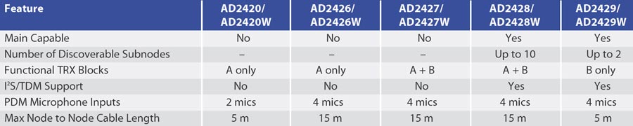
Table 1. A2B Transceiver Feature Comparison — © ADI
The AD2427W and AD2426W offer reduced (subnode only) functionality and are primarily targeted for microphone connectivity applications such as hands-free, ANC/RNC, or ICC. The AD2429W and AD2420W are entry-level A2B derivatives that offer significant cost advantages relative to their full-featured counterparts and are particularly well-suited for cost-sensitive applications such as automotive eCall and multi-element microphone arrays. Table 1 shows a feature comparison among the third-generation A2B transceivers.
The AD242x series supports daisy-chaining a single main plus up to 10 subnodes over a total bus distance of 40 m with up to 15 m supported between individual nodes. A2B’s daisy-chain, line topology is an important advantage over existing ring topologies as it relates to overall system integrity and robustness. If one connection of the A2B daisy chain is compromised, the entire network does not collapse. Only those nodes downstream from the faulty connection are impacted by the failure. And A2B’s embedded diagnostics can isolate the source of the failure, signaling an interrupt to initiate corrective action.
A2B’s main/subnode line topology is inherently efficient when compared to existing digital bus architectures. After a simple bus discovery process, zero additional processor intervention is required to manage normal bus operation. As an added benefit of A2B’s unique architecture, system latency is completely deterministic (a 2-bus cycle delay, which is less than 50 µs) irrespective of the audio node’s position on the A2B bus. This feature is extremely important for speech and audio applications such as ANC/RNC and ICC, where audio samples from multiple remote sensors must be processed in a time-aligned fashion.
All A2B transceivers deliver audio, control, clock, and power over a single, 2-wire, UTP cable. This reduces overall system cost for a variety of reasons.
- The number of physical wires is reduced relative to traditional implementations.
- The actual wires themselves can be lower cost, lower weight UTP as opposed to more expensive shielded cables.
- Jumper wires Most importantly, for particular use cases, A2B technology offers a bus power capability that delivers up to 300 mA of current to audio nodes on the A2B daisy chain. This bus power capability eliminates the need for local power supplies at the audio ECU—further reducing total system costs.
The total 50 Mbps bus bandwidth delivered by A2B technology supports up to 32 upstream and up to 32 downstream audio channels using standard audio sample rates (44.1 kHz, 48 kHz, etc.) and channel widths (16-, 24-bit). This pro- vides significant flexibility and connectivity to a wide range of audio I/O devices. Maintaining a completely digital audio signal chain between audio ECUs ensures that the highest quality audio is preserved without introducing the potential for audio degradation via ADC/DAC conversion.
System-level diagnostics are an essential component of A2B technology. All A2B nodes have the capability to identify a variety of fault conditions including opens, wires shorted together, reversed wires, or wires shorted to power or ground. This capability is important from a system integrity standpoint because, in the case of opens, wire shorts, or reversed wire faults, A2B nodes are still fully functional upstream of the fault. The diagnostic capability also provides for the efficient isolation of system-level failures, which is critically important from the dealer/installer standpoint.
The recently announced, fourth generation of A2B transceivers, AD243x, builds upon the existing technology foundation by increasing key functional parameters (node count increased to 17, bus power increased to 50 W) while adding an additional SPI-based control channel (10 Mbps) that provides an efficient software over-the-air (SOTA) capability for remote programming of intelligent A2B-connected nodes. The new features provided by the AD243x family make it well-suited for LED-fitted microphone nodes in super-premium microphone architectures.
Applications of A2B Microphones and Sensors in the Automotive Industry
From a single voice microphone to a multi-element BF mic array for HF communication, from ANC to RNC, from ICC to siren sound detection, microphones have found more and more applications in the automotive industry. In accordance with the technology and market trend, almost every single new vehicle that hits the road today is equipped with at least one microphone module for HF communication. Premium and luxury cars may come with six or more microphone modules that are necessary for realizing the full potential of BF, AEC, ANC, RNC, ICC, and so on, where digital MEMS microphones present clear advantages.
The growing microphone count presents one significant challenge to vehicle infotainment engineers—how to simplify the connecting harnesses and minimize their weight. This is not a trivial task for traditional analog systems. At a minimum, an analog microphone requires a pair of two shielded wires (ground and signal/ power), pins, and connector cavities for interconnection. The amount of wires is always twice the number of microphone modules in the system. Meanwhile, the total weight of the harness could increase even more rapidly depending on the wire length that is needed for connecting each microphone module. One simple way to mitigate this problem is to reduce the number of microphones used in the system by sharing a microphone signal among multiple applications. For example, the same microphone signal could be used in HF communications and as an error signal in the ANC system. However, different applications may require different microphone characteristics. In the previously mentioned example, an HF microphone signal often prefers to have a rising frequency response shape (that is, sensitivity decreases with decreasing frequency) to remove the low frequency noise content inside the cabin. This is a helpful and very effective technique to improve the speech intelligibility delivered by a voice microphone. On the contrary, an ANC microphone requires sufficient sensitivity level at low frequencies as the main purpose of the ANC algorithm is to reduce the low frequency noise. Thus, to share the same microphone in two applications in an analog system, the signal coming from the microphone needs to be fed into different circuits for proper frequency filtering. In this case, one or multiple ground loops may form, which can cause significant noise issues.
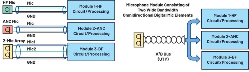
Figure 3. (Left) Analog system design with analog mic elements (shielded wires). (Right) Digital system design with digital mic elements (A2B technology and UTP wires). — © ADI
As a digital bus with daisy-chaining capability, A2B technology together with the digital MEMS microphone provide a well-suited solution for interconnecting and/or sharing multiple microphone signals demanded by audio, voice, noise cancelling, and other acoustic applications that are rapidly expanding in vehicles. Consider an imaginary while exemplary case where a car application calls for an HF microphone module, an ANC microphone module, and a simple array microphone module consisting of two microphone elements for BF, and all three modules are integrated around the overhead console area. Figures 3a and 3b show how such a design may be realized with the traditional analog and the digital A2B systems, respectively.
Since the analog system cannot easily accommodate microphone sharing, each application block (HF, ANC, and BF) requires dedicated microphone(s) and separate harnesses for connecting to the corresponding functional circuit(s). This leads to four separate microphone elements and three sets of harnesses (a total of seven wires plus shielding). In contrast, because sharing signals is easily supported by the digital A2B system, the number of microphone elements can be potentially reduced from four to two. In this specific example, a single micro- phone module consisting of two wide bandwidth omnidirectional microphone elements can be used to provide two channels of acoustic signals that cover the needs of all application blocks. Once these two channels of signals reach the center processing unit (for example, the head unit or amplifier) through a simple UTP wire, they can then be shared and digitally processed to support HF, ANC, and BF applications.
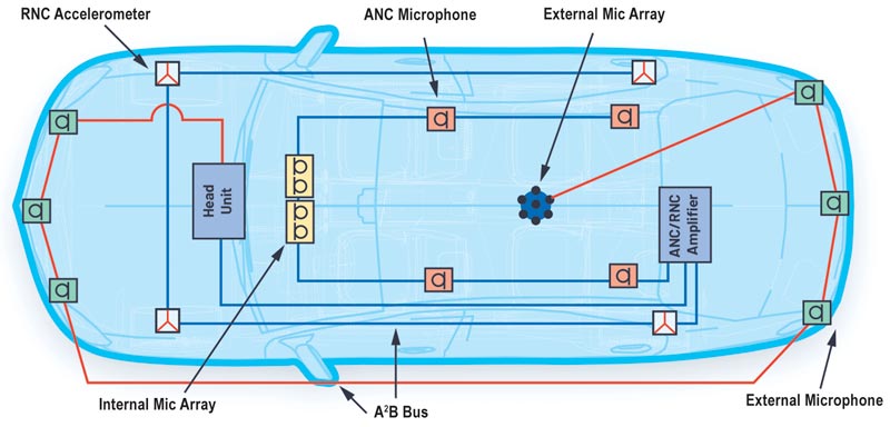
Figure 4. Common A2B microphones and sensors. — © ADI
Although the example illustrated in Figure 3 may not represent a real situation, it clearly demonstrates the benefits of the A2B technology over the traditional analog technology. A digital audio bus system like the A2B technology addresses the challenge of automobile manufacturers to offer new audio and acoustic- related concepts that enhance user experience and allows these concepts to be brought to the market for faster implementation.
Indeed, many applications that are either new to the automotive market or previously difficult to implement have been made possible by the commercialization of A2B technology. For example, as a leading automotive audio solution provider, Harman International has developed a family of digital microphone and sensor modules that takes advantage of the A2B system to enable various automotive applications. Figure 4 shows some common automotive A2B microphones and sensors and how they can be used on a vehicle. These sensors include single A2B microphones and multi-element microphone arrays for ANC and voice communication, A2B accelerometers for RNC, externally mounted bumper A2B microphones, and rooftop A2B microphone arrays for emergency siren detection and acoustic environment monitoring. Enabled by these A2B microphones and accelerometers, more and more application solutions requiring multiple sensor inputs are currently under development to further enhance the user experience in the automotive industry.
Summary
Vehicle architectures of the future will become increasingly more dependent on high performance acoustic sensing technology such as microphones and accelerometers. A completely digital approach including sensor, interconnect, and processor provides significant performance and system cost benefits. Analog Devices and Harman International are partnering to deliver cost-effective solutions that create value and differentiation for their end customers.
Authors:
Ken Waurin, Strategic Marketing Manager at Analog Devices Inc.
Dietmar Ruwisch, Senior Audio Technologist at Analog Devices, Inc.
Yu Du, Senior Principal Acoustic Engineer at Harman International Industries
About the Authors
 Ken Waurin is a strategic marketing manager at Analog Devices, where he has overall responsibility for Automotive Audio Bus (A2B) technology. Since joining ADI in 1996, he has held product management, business development, tactical, and strategic mar- keting roles that span multiple technology areas including DSP, MEMS, converter, video, and connectivity. His primary focus is on automotive infotainment and emerging applications driving vehicle differentiation such as premium audio, road noise cancellation, and in-vehicle zonal communications. He can be reached at: kenneth.waurin@analog.com.
 Dietmar Ruwisch is a senior audio technologist at Analog Devices. He studied physics in Münster, Germany, and received his doc- torate in 1998 with a thesis on artificial neural networks. Since then his key area has been audio signal processing, where he holds several patents. His focus is on improving the quality of audio communication—whether between humans or with a machine—and the corresponding processing of microphone and microphone array signals. He can be reached at: dietmar.ruwisch@analog.com.
 Yu Du is a senior principal acoustic engineer at Harman International Industries. He holds both a B.S. and M.S. degree in vehicle engineering from Tsinghua University (Beijing, China) and received his Ph.D. in mechanical engineering from Virginia Tech (Blacksburg, Virginia). His R&D experience extending over more than 20 years in various fields of acoustics includes structural acoustics, active and passive vibration and noise control, MEMS transducer design and simulation, hearing science, and acoustic signal processing. His current work at Harman focuses on advanced microphone and sensor technology development for automotive applications. Dr. Du is a member of The Acoustical Society of America (ASA), The Audio Engineering Society (AES), and The American Society of Mechanical Engineers (ASME). He currently serves on the AES Technical Committee for Automotive Audio.
![]()
Visit: https://ez.analog.com
Contact Romania:
Email: inforomania@arroweurope.com
Mobil: +40 731 016 104
Arrow Electronics | https://www.arrow.com
![]()