


The NK-2.4Y 2.4 GHz module by Circuit Design Inc is a telecommand module developed for transmitting switching signals. To ensure reliable and secure communication, the NK-2.4Y incorporates CRC error detection that achieves a Hamming Distance of 6. This prevents malfunction of the system due to errors.
 What is error detection?
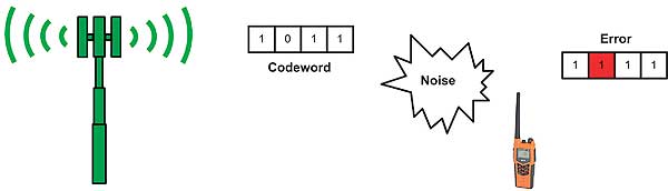
In any communication medium there will always be noise and interference present. In particular RF is constantly surrounded by noise and interference from other signal sources. In analogue communication, noise occurs as permanent artefacts in the signal and cannot be removed. The combination of signal with noise means the receiver cannot properly read the signal and respond correctly.
By adding extra bits (redundancy bits) to the data, the receiver can look at these extra bits and analyse the data to determine if an error has occurred during transmission.
 Error detection and correction
When the receiver analyses the data, it can detect the occurrence of errors, but cannot always determine which bits have been corrupted. This process is error detection. If the receiver can detect and identify the positions where the error occurred, it can correct the affected bits. This is called error correction and allows communication to continue normally.
Hamming distance
When implementing Hamming, the receiver stores a table of all valid bit codes (codewords) used in the transmission. To change one codeword into another, we flip bits. The number of bit flips equals the Hamming Distance.
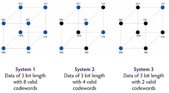
For data length of 3 bits, every codeword between 000 to 111 (i.e. 000 -> 001…111) can be shown visually using a grid with 8 points. For other data lengths, each will produce its corresponding grid. Every movement along a line represents one bit change or Hamming distance of 1. Valid codewords in a system can be highlighted in blue.
The minimum hamming distance is the minimum number of moves to get from one codeword to another. When we talk about the Hamming Distance, it is usually referring to this minimum value. For example in System 3 above, the shortest path to reach another codeword is in 3 shifts. Let us look at each system in turn.
 In system 1, all codewords are treated as valid and no error detection is possible. A shift from a valid codeword will just produce another valid codeword.
In system 2, to move from one valid codeword to another involves passing through exactly 1 invalid codeword. The total move is a Hamming minimum distance of 2. The receiver can flag a 1 bit error occurrence when the codeword lands on the invalid points, but as this invalid codeword lies exactly halfway between 2 valid codewords, it cannot determine the correct codeword that was sent. So no error correction is possible here.
In system 3, the minimum distance between the 2 valid codewords is 3. A 1 bit or 2 bit error occurrence can be flagged, but not a 3 bit error occurrence (just shifts to another valid codeword). However we can see that the system now can correct a 1 bit error by looking at the nearest valid codeword beside it and determining that was the one that was sent.
So we want to increase the Hamming distance to make a reliable communication system. To do this you can use fewer valid codewords or use more bits. The cost of doing this of course is sending larger amounts of data in a communication medium with fixed capacity.
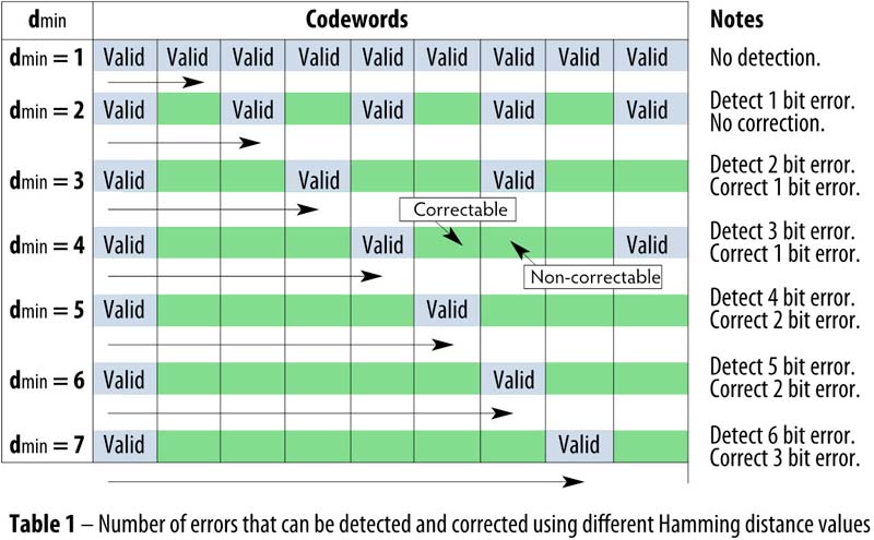
We can expand the above and generalise what would happen with larger Hamming distances. Let us organise the codewords into a table (table 1). The Hamming distance defines the space between valid codewords. All invalid codewords are in green squares.
 Communication errors
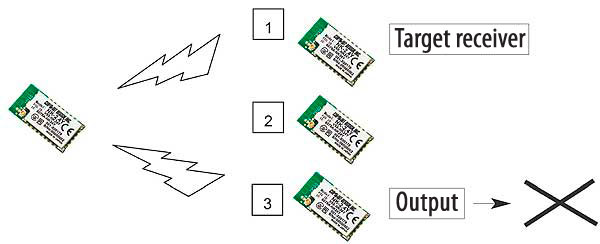
It is assumed that transmitting switching data is a simple application of radio and not require complex design. However, there will be the case where multiple receivers are present and there needs to be precise control over which receivers should respond.
We can show below:
For example we send a signal to tell receiver 1 to respond. If data is misinterpreted, the wrong receiver (receiver 3) will operate which compromises safety of the system.
Hamming distance and NK-2.4Y
In the beginning we explained the basic idea of how data error can be detected (and possibly corrected) using Hamming function.
When implementing Hamming function in practice, there are various techniques. The Hamming function performed on the NK-2.4Y payload data is derived from the CRC method and does not use specific codewords as above. The NK-2.4Y CRC (cyclic redundancy check) is used as a method of error detection and consequence of this is that a Hamming Distance of 6 is achieved.
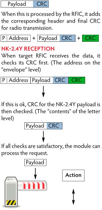
Secondly for radio communication purposes, the RFIC by default adds its own CRC on the final data before transmission. The only purpose of this is to ensure that the payload reaches the target module. It does not guarantee cohesion of the NK-2.4Y payload data. This is why a separate CRC (with Hamming distance 6) is performed on just the NK-2.4Y payload data to guarantee correct data communication.
The analogy is to imagine how letters are posted. The address on the envelope is written in a standard format so that the recipient can receive it.
The content of the envelope is irrelevant. If the address is unreadable it does not get delivered. This is equivalent to the CRC done by the RFIC.
When the envelope reaches the recipient, its contents can be examined.
This is equivalent to the NK-2.4Y CRC and Hamming function done on the NK-2.4Y payload when the data is received by the target RFIC.
NK-2.4 Payload
Below is the NK-2.4Y payload data with its NK-2.4Y CRC (Hamming distance 6) check data added:
 Conclusion
We have seen in the previous diagram what can happen if no CRC or any check is performed on the payload. By incorporating CRC and therefore Hamming distance on the payload, secure and reliable communication is possible. Any errors detected, all receivers will discard the data and none will output any signal. This prevents malfunction of the system due to errors. As transmission is continuous NK-2.4Y does not perform error correction, it can simply wait for the next transmission packet.
Remark
According to IEC 870-5-1 “Telecontrol equipment and systems Part 5 Transmission protocol Section One – Transmission frame formats”, Hamming distance 6 is recommended for format class FT3 which are suited for systems with particularly high data integrity requirements.
Author: John Bell
Circuit Design GmbH
info@circuitdesign.de | www.circuitdesign.de