


The effective use of COTS solutions and manufacturer development kits reduces the learning curve for implementing new technologies and enables embedded products to get to market faster, explains Martin Hill of Microchip Technology.
The latest generation of microcontrollers (MCUs) offers designers higher integration and a wider range of peripherals and functions which demand a wider range of design skills for successful implementation. The good news, however, is that MCU manufacturers, such as Microchip Technology, are investing in resources which enable engineers to quickly gain the necessary embedded design skills, or significantly reduce the learning curve for implementing new technologies.
Microcontrollers are blurring the boundaries which once separated the design disciplines of software engineering and hardware engineering: traditionally, software engineers designed application software for microprocessors; whilst hardware engineers created microprocessor-based systems by combining an MCU and external components. The introduction of the first high-integration MCUs changed this. They replaced the significant engineering effort required to develop a design from an MCU, external memory, peripheral, interface and discrete circuits, with the need for hardware engineers to write firmware for low-level driver-type applications.
Microcontrollers and more
This means that embedded engineers need to add proficiency in C and Assembly language as well as debugging to their existing skills of hardware circuit design, microcontroller interfacing, PCB layout, design for manufacture and a detailed knowledge of EMC/EMI and other regulatory standards and product approvals.
It is hardly surprising, therefore, that embedded engineers are increasingly looking to gain a competitive edge and get products to market faster. That is why the availability of software libraries, sub-systems and advanced development tools has become an essential part of the MCU selection process.
This article discusses a number of scenarios and suggests application-based strategies for choosing the right microcontroller and using the manufacturers’ tools and resources to simplify implementation and reduce time to market.
Blurring the boundaries of MCU performance
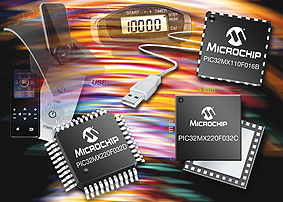
Microcontrollers provide an extremely wide spectrum of computing power and peripheral integration and the choice is widened still further with high-performance cores, such as the PIC32MX1 and MX2 MCUs, being offered in reduced pin-count packages. Developments such as this mean that high-performance MCUs are moving into applications which would once have been the domain of the more established cores.
Higher levels of integration also present designers with complex trade-offs: performance enhancements such as faster or improved cores can deliver plenty of MIPs, but very high levels of analogue functionality can reduce real-time performance.
Of course, device fit, form and function is only part of the selection process. There are other factors and decisions which can have a significant impact, such as design strategy, time to market, vendor support and cost. The questions which must be asked are: “Could COTS solutions help to shorten time to market?”, and “Which design strategy will provide the fastest design cycle?”.
The foundations of embedded designs
Typically, embedded systems need a user interface, display and some form of connectivity and these fundamentals have not changed over the years. Their complexity, however, has increased, whilst the cost has reduced. This means that a colour graphics LCD, touch interface and wireless connectivity are now considered essential if a product is to be competitive. There are, of course, still valid reasons for selecting more traditional segmented LCDs, mechanical type switches for the user interface and wired connectivity, however, fashion sells and customers can be fickle which makes these design decisions crucial to the financial success of the design for a consumer electronic product.
Bridging the skills gap
In a fast-paced market, new and improved technologies can come along just as the designer has mastered the skills introduced by the previous technology breakthrough.
Fortunately, commercial off the shelf (COTS) solutions can support rapid product development by bridging the skills gap. COTS solutions can take many forms. These can include source code and configuration tools for implementing a communication protocol stack, through to a full software development framework including a RTOS, peripheral driver support libraries, system timing analysis, optimised for a specific application, such as automotive. It is becoming increasingly impractical to being a new design by writing all of the required code and starting hardware development from scratch. Some industries, such as automotive, actively discourage this ‘blank canvas’ design strategy by specifying the software development tools which must be used during development.

Silicon vendors and third-party development tools are also moving designers away from an ‘all-my-own-work’ approach by supplying, for example, a free GUI to ease debugging and tuning of a specific application such as motor control or a touch interface.
Another way to achieve higher integration and a faster time to market is to link new microcontroller peripherals to other peripherals to form sub-systems. Touch-screen applications can, for example, be implemented with a Charge Time Management Unit (CTMU), or using the Capacitive Voltage Divider (CVD) technique, and both could be linked with an analogue MUX to form a sampling sub-system for multiple touch buttons or linear and rotary sliders. Another example would be to use a Parallel Master Port (PMP) to drive a Low Cost Controller-less (LCC) graphics panel or using an integrated graphics controller.
New general-purpose peripherals, such as the Configurable Logic Cell (CLC) can also be used to reduce the external component count. Designed to link with a range of other internal peripherals, CLCs are a useful addition to the embedded engineer’s tool-kit. Integrated high-speed comparators and op amps are also particularly useful real-time system components for power-supply and motor-control applications.
Resources to reduce time-to-market
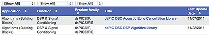
Application notes, as well as other COTS solutions and tools, support new applications and peripherals and help to speed time to market by reducing the need for embedded designers to re-invent the wheel. Microchip, for example, offers one of the widest ranges of support resources including development boards and applications libraries focussed on specific applications and product families.
Similarly, code examples address specific problems ranging from initialising peripherals to implementing algorithms. All of these resources can be found on the Microchip website.
Implementing a touch interface
The design strategy, and the tools which will be most helpful in reducing time to market, will depend on the specific challenges presented by each design.
Take for example, the challenge of implementing a new touch-screen interface to replace the mechanical push-buttons on an existing kitchen-top appliance design using a PIC16 to drive a motor and a segmented LCD.
Clearly, the first goal would be to re-use as much of the existing design as possible: if the existing code is written in Assembly language, the aim should be to find a developed touch solution in a higher-level language. This would deliver a fast design process and overcome any in-house skills gap.
Typically, the strategy for this design would be as follows:
• Select a microcontroller from the same general product family which provides the basis for compatibility, or partition the design using two microcontrollers;
• Select a microcontroller with the peripherals required to provide the new functionality and memory, as well as analogue support to reduce component count;
• Look for a COTS solution which uses C code for the touch interface;
• Re-use and mix the existing Assembler code and C code for the new functionality, but partition the design into separate files. Alternatively, partition the design using separate microcontrollers with communications support for interfacing between them;
• After porting the code, run the application without the additional functionality and test the behaviour;
• Design and debug the touch interface using support tools;
• Environmentally test the touch interface and then integrate with the complete application and re-test.
A potential real-world solution to this design would be to:
• Contact Microchip for advice on specific application requirements;
• Visit the Touch Design Centre at http://www.microchip.com/mtouch
• Evaluate different touch-screen options using a touch-screen development board;
• Use the free Microchip Advanced Parts Selector (MAPS) to identify suitable parts for the design migration;
• Follow the design guidelines for designing a touch interface using Microchip application note AN1102 and other online resources. Request additional support from Microchip if required;
• Use the free Microchip CVD Framework COTS software package which is part of the Microchip Applications Libraries (MAL) to design and debug the touch interface. At this stage, also select a suitable debugging tool;
• Use the XC8 Microchip C Compiler and MPLABX IDE to construct and debug the combined application firmware;
• Environmentally test the design. Microchip maybe able to assist with some qualitative EMC testing and further design guidance if required.
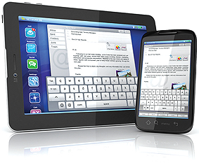
Interfacing to smart phones or tablets
Designing a new accessory for a smartphone or tablet computer presents different challenges, such as the need to connect to Android® or Apple® phones or tablets, in addition to charging, control and other functions. Given the fast-paced nature of this market, a rapid design cycle is imperative.
The overall design strategy would be to:
• Research support for the Apple and Android platforms;
• Determine the overall application memory and resource requirements;
• Look for a COTS solution for the phone/ tablet interface;
• Consider contracting-out the interface design if the skills are not available in-house;
• Select a microcontroller which supports the appropriate COTS software framework;
• Develop the accessory and the interface.
Again, using online resources and development tools can help to take time out of this design cycle:
• Visit the pages: www.microchip.com/apple and www.microchip.com/android
• Contact Microchip for advice on specific application requirements;
• Obtain any applicable license(s) directly from Apple®. A license is not required for Android®;
• Choose a development board with relevant demos;
• Decide whether to download the free, standard or professional version of the XC16 or XC32 C Compiler;
• For Android, download the free Android Framework COTS software package which is part of the Microchip Applications Libraries (MAL). Use the appropriate COTS software package, XC C Compiler and MPLAB X IDE to develop and debug the accessory interface;
• Request additional support from Microchip if required.
The brief for a new design for a smart meter would probably include a QVGA colour graphics display, an over-laid resistive touch display panel, radio link to a remote sensor and WiFi connection to the internet.
Minimising software development time would be critical as the design would also need a RTOS to perform task scheduling and resource management.
The typical design strategy would be to:
• Use high-level language;
• Make extensive use of COTS RTOS, communication protocol stacks and support libraries/ tools;
• Adopt a modular approach to the hardware design;
• Provide a clear roadmap for the design to become the basis for additional products.
To take reduce the time to market for a smart meter, the approach could be to:
• Contact Microchip for advice on specific application requirements;
• Visit http://www.microchip.com/rtos for guidance on RTOS support and selection;
• Evaluate the microcontroller and multi-media options with a PIC32, PIC24 or dsPIC33E Starter Kit with a multi-media expansion development board;
• Follow the strategy outlined in the application note AN1264 ‘Integrating Microchip Libraries with a Real-Time Operating System’;
• Use the multiple stacks available in the Microchip Applications Library or request additional support from Microchip;
• Develop and debug the combined application firmware using the XC16 or XC32 Microchip C Compiler and MPLAB X IDE.
Summary
Embedded systems are becoming more complex but, for many designs, COTS solutions from Microchip enable a fast time to market, and can even minimise the need for designers to undertake the steep learning curve introduced with each new technology. These design resources, such as online design centres, code examples, application notes, development boards and more, have become an essential part of the tool-kit for innovative embedded design and a critical factor in microcontroller selection.
www.microchip.com