 Introduction to Condition-Based Monitoring
The global condition-based monitoring (CbM) market has experienced significant growth over the past few years, and this looks set to continue.1 This growth coincides with the rapid advancement of MEMS accelerometers for use in vibration sensing applications, now rivaling the once dominant piezoelectric or PZT accelerometer. There is an increased demand for CbM on less critical assets as well as a growing adoption rate of wireless CbM systems, and MEMS accelerometers are the key to this. This article will compare MEMS accelerometers to piezoelectric accelerometers to highlight just how far MEMS sensors have come in their short lifetime. Key design considerations for MEMS accelerometers in CbM applications will also be discussed with a comparison of five MEMS sensors from three different vendors.
The Current State of the Art in Vibration Sensing—MEMS vs. Piezoelectric
Vibration sensors have been used to detect machine health as far back as the 1930s. Even now vibration analysis is considered the most important modality for predictive maintenance (PdM). Piezoelectric accelerometers have been long established as the gold standard vibration sensor used on the most critical assets to ensure they remain operational and perform efficiently. Until recently, MEMS accelerometers’ limited bandwidth, noise performance, and g-range capabilities prevented their use in CbM of critical assets. While many high g-range accelerometers are available (designed specifically for automotive impact detection), they have very limited noise performance and bandwidth, making them unsuitable for CbM. Likewise, some low noise MEMS accelerometers (designed specifically to detect tilt) are available but have insufficient bandwidth and g-range.
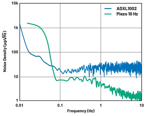
A small number of MEMS manufacturers have been striving to overcome the noise, bandwidth, and g-range shortcomings and as such have produced several medium and high performance MEMS accelerometers with the latter being comparable to piezoelectric accelerometers. MEMS sensors are based on a completely different principle of operation to piezoelectric sensors, and this is where the key differences arise. Figure 1 shows how MEMS can measure down to dc, allowing measurements from very slow rotating machinery as well as tilt detection. It is clearly understood that piezoelectric sensors can offer better noise performance than MEMS at higher frequencies, but at low frequencies MEMS sensors offer lower noise all the way to dc. Being able to measure these low frequencies is very useful for wind turbines, and other types of slow rotating machinery used in metal processing, pulp/paper processing, and food/beverage industries where slow rotating speeds of assets below 60 rpm (1 Hz) are common.
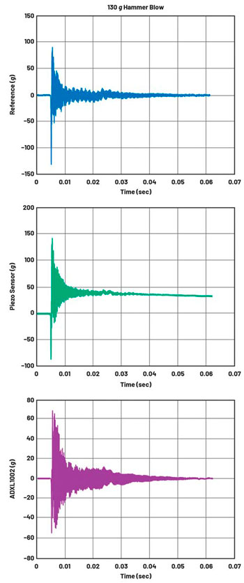
Figure 2 shows that when piezoelectric sensors are exposed to large shock events they can saturate, and due to the large RC time constant they can take a long time to settle back to normal. MEMS, on the other hand, matches the noncontact reference sensor by settling back to normal almost instantly. The implications with a piezoelectric sensor undergoing a severe shock mean there is a risk that valuable information or failures in the asset/process could go undetected, while MEMS sensors will detect impact events and subsequent events reliably.
| Sensor | Cost 1k u.p. | Noise | 3 dB Bandwidth |
Potential Battery Life |
DC Response |
Self-Test | Integrated Features |
| Piezoelectric Accelerometer |
$25 to $500+ | <1 µg/√Hz to 50 µg/√Hz |
2.5 kHz to 30 kHz+ |
Short to medium |
No | No | No |
| MEMS Accelerometer |
$10 to $30 | 25 µg/√Hz to 100 µg/√Hz | 3 kHz to 20 kHz+ |
Medium to long |
Yes | Yes | Yes |
Table 1. Comparison of Piezoelectric and MEMS Accelerometers for CbM Applications
Table 1 highlights some more advantages of MEMS accelerometers for CbM applications.2 Piezoelectric accelerometers are less suitable for wireless CbM systems due to a combination of size, power consumption, and a lack of integrated features, but solutions do exist with typical consumption in the range of 0.2 mA to 0.5 mA.
MEMS accelerometers also have a self-test feature where the sensor can be verified to be 100% functional. This could prove useful in safety critical installations where meeting system standards is made easier by the ability to verify if a deployed sensor is still functional. In some applications this feature is one of the most important as it allows maintenance professionals to know with absolute certainty the current state of the asset as well as the accuracy and reliability of what they are measuring.
Design Considerations for MEMS Accelerometers in CbM Applications
MEMS accelerometers designed specifically for CbM applications have some different characteristics compared to general-purpose accelerometers. In this section we will discuss the key data sheet parameters of MEMS accelerometers suitable for CbM and how they relate to detecting machine faults. For example, how can we select a sensor with the correct g-range or noise performance to detect bearing faults on a 300 kW induction motor? Table 2 shows a list of the most important specifications for five MEMS accelerometers targeted at CbM applications. Each specification will be discussed in detail in the following sections.
| ADXL1002 | ADXL317 | Other MEMS Vendors | |
| No. Axes | 1 | 3 | 3 |
| ±3 dB Bandwidth | 11 kHz | 4 kHz (x, y) 2 kHz (z) |
2.9 kHz to 8.5 kHz |
| Resonance | 21 kHz | 5.1 kHz (x, y) 3.1 kHz (z) |
Not listed, or up to 7 kHz |
| Noise Density | 25 µg/√Hz | 55 µg/√Hz (x, y) 120 µg/√Hz (z) |
75 µg/√Hz to 300 µg/√Hz |
| g-Range | 50 g | 16 g | 2 g to 64 g |
| Cross-Axis Sensitivity | 1% | 1% | Not listed, or up to 2% |
| Temperature Range | –40°C to +125°C | –40°C to +125°C | –40°C to +105°C |
| Solutions for Attaching MEMS to Machines | Yes | No | No |
Table 2. Comparison of Most Suitable MEMS Accelerometers for CbM
Bandwidth
The bandwidth of a vibration sensor is typically linked to the criticality of the asset it will be monitoring. A critical asset or motor is crucial to keeping a process or larger machine operational and online. If such an asset were to break down, it would lead to unplanned downtime and potential loss of revenue. In order to detect and diagnose faults as early as possible, and avoid unplanned downtime, it is imperative to have a wide bandwidth and low noise vibration sensor. Low noise is required to detect faults or deviations at low magnitudes and wide frequencies, as common faults with bearings, gear meshing, and pump cavitation all occur—or at least can be detected earliest—at higher frequencies greater than 5 kHz and even up to 20 kHz and beyond. Therefore, it is incumbent on MEMS sensors to be able to compete with the de facto vibration sensors used for decades in industrial applications: piezoelectric accelerometers. A noise level of less than 100 µg/√Hz and bandwidth of 5 kHz or greater is considered a high performance MEMS accelerometer for CbM. Table 3 categorizes the two most important criteria for MEMS accelerometers used in CbM and PdM applications.3
| MEMS Accelerometer Performance | Noise | Bandwidth |
| High | <100 µg/√Hz | >5 kHz |
| Medium | >100 µg/√Hz and <1000 µg/√Hz |
Up to 5 kHz |
| Low | >1000 µg/√Hz | Up to 1 kHz |
Table 3. MEMS Accelerometer Performance Criteria for CbM Applications
Not all sensors are required to be ultralow noise or wide bandwidth; there are levels to vibration sensing that depend on how critical it is to keep an asset running. Water cooling pumps in a nuclear reactor could be considered extremely critical and, in this case, detecting a fault early is required. This means the criticality of the asset to be monitored will generally dictate the level of vibration sensor required, which relies on the following criteria.
Fault Detection
To simply detect if vibrations have gone above a threshold or warning level, a low performance MEMS accelerometer can be used. This method is typically employed on lower criticality assets.
Fault Diagnosis
To detect and identify the potential source(s) of the fault, a higher level of MEMS accelerometer is required along with algorithms.
Fault Prediction
This requires the highest level of MEMS accelerometer performance in order to detect issues at the earliest possible time and allow algorithms to identify the source of the fault. This also requires good domain knowledge of the asset.
Fault Prognosis
This is the highest level of PdM requiring the best MEMS accelerometers along with algorithms, machine learning, etc., as well as expert domain knowledge of the asset. The aim of fault prognosis is to have the PdM system make recommendations to prolong the life of the asset or even optimize the performance of the asset.
Keep in mind the performance level of the predictive maintenance sensor used on an asset is linked to the importance or criticality of that asset remaining online and not at the cost of the asset itself.
Table 4 shows the range of available bandwidths of the MEMS accelerometers most suitable for CbM. Due to their mechanical nature, various moving silicon elements, and integrated conditioning electronics, it is not easy to make a wide bandwidth MEMS accelerometer, especially with low noise. Typically, the mechanical resonance is several kHz away from the bandwidth of interest. Recently, several MEMS accelerometers have managed to move the usable bandwidth closer to the mechanical resonance with enhanced filtering methods. However, some manufacturers still choose not to state the resonant frequency of their vibration sensors, which suggests it is either very close to the usable bandwidth or reveals sensitive information on how their part works.
| ADXL1002 | ADXL317 | Other MEMS Vendors | |
| Bandwidth | 11 kHz | 4 kHz/2 kHz | 2.9 kHz to 8.5 kHz |
| Resonance | 21 kHz | 5.1 kHz/3.1 kHz | Not listed, or up to 7 kHz |
Table 4. Bandwidth and Resonance of MEMS Accelerometers for CbM
Noise Density
MEMS accelerometer noise comes from several inherent sources such as flicker noise, Brownian noise, or electronics noise. It is usually expressed in µg/√Hz. The noise output from a MEMS accelerometer is dependent on the output filter settings shown in Table 5. Some data sheets specify rms noise, but be careful as this will often be over a very small bandwidth.
| Filter Order | Coefficient |
| First | 1.57 |
| Second | 1.11 |
| Third | 1.05 |
| Fourth | 1.025 |
| Brick Wall | 1 |
Table 5. Filter Order Coefficient Used in Calculation of MEMS Accelerometer Noise
The output rms noise of a MEMS accelerometer can be determined by the following formula:
Once the sensor noise is understood, it is important to match the most suitable sensor to the machine type, keeping in mind some important questions such as: Will the sensor’s noise prohibit it from measuring important vibrations, and will the g-range of the sensor be able to withstand potential fault vibration levels? Luckily, there are standards that can help with this such as ISO 10816.
ISO 10816 establishes conditions and procedures for the measurement and evaluation of vibrations from assets and machines. It defines a vibration severity standard where the rms velocity (10 Hz to 1 kHz) of the installed machine’s housing is used as a condition indicator, as shown in Table 6. The measured vibration from the machine is classified based on machine size, mounting strategy, and machine class (I = small, II = medium, III = large with small foundation, and IV = large with rigid foundation).
| RMS Vibration Velocity (mm/s) | Class I | Class II | Class III | Class IV |
| 0.28 | A | A | A | A |
| 0.45 | ||||
| 0.71 | ||||
| 1.12 | B | |||
| 1.8 | B | |||
| 2.8 | C | B | ||
| 4.5 | C | B | ||
| 7.1 | D | C | ||
| 11.2 | D | C | ||
| 18 | D | |||
| 28 | D | |||
| 45 |
Table 6. ISO 10816 Vibration Severity Chart
■ A—Recently Commissioned Motor Installation
■ B—Unlimited, Satisfactory, Long-Time Operation
■ C—Short-Time Operation
■ D—Vibration Level That Causes Damage to the Motor
Please note that accelerometers typically output acceleration in g whereas ISO 10816 uses velocity in mm/s or in/s. Equation 2 can help us translate accelerations in g to velocity in mm/s. It determines that at a minimum vibration frequency of 10 Hz, the noise in the acceleration measurement must be less than 7.18 mg to detect vibration severity in the good range (A) for a Class 2 machine, per ISO 10816-1 (VMIN = 1.12 mm/s) as shown in Table 6.4
Equation 3 offers this in a generic form, along with an example, which estimates the total noise associated with an accelerometer with a noise density of 80 μg/√Hz, when using it with a single-pole low-pass filter that has a cutoff frequency of 1000 Hz (fC = 1000 Hz). At 3.17 mg, the accelerometer appears to meet the boundary condition from Equation 2:
Table 7 shows the prescribed vibration levels for each class of machine from a known good state to dangerous fault level vibrations and the corresponding minimum noise a MEMS accelerometer requires to detect known good vibrations in region A (Class I at 4.5 mg, Class II at 7.2 mg, Class III at 11.5 mg, and Class IV at 17.9 mg).
| Minimum Noise Required | |||||||
| Noise Density (µg) |
Bandwidth (Hz) |
Sensor Noise (mg) |
Class I 0.71 mm/s 4.5 mg |
Class II 1.12 mm/s 7.2 mg |
Class III 1.8 mm/s 11.5 mg |
Class IV 2.8 mm/s 17.9 mg |
|
| ADXL1002 | 25 | 10,000 | 3.1 | Pass | Pass | Pass | Pass |
| ADXL317 [X, Y] | 55 | 4000 | 4.4 | Pass | Pass | Pass | Pass |
| ADXL317 [Z] | 120 | 2000 | 6.7 | Fail | Pass | Pass | Pass |
| MEMS B [X, Y] | 75 | 6300 | 7.5 | Fail | Fail | Pass | Pass |
| MEMS B [Z] | 110 | 6300 | 10.9 | Fail | Fail | Pass | Pass |
| MEMS C1 [X, Y] | 130 | 4200 | 10.6 | Fail | Fail | Pass | Pass |
| MEMS C1 [Z] | 130 | 2900 | 8.8 | Fail | Fail | Pass | Pass |
| MEMS C2 [X] | 300 | 8200 | 34.0 | Fail | Fail | Fail | Fail |
| MEMS C2 [Y] | 300 | 8500 | 34.7 | Fail | Fail | Fail | Fail |
| MEMS C2 [Z] | 300 | 5600 | 28.1 | Fail | Fail | Fail | Fail |
Table 7. Noise Comparison of MEMS Accelerometers for CbM as per ISO 10816 Vibration Severity Standards
This data suggests that MEMS C2, MEMS C1, MEMS B, and ADXL317 (z-axis) are not suited for use on machines where a noise level below 0.71 mm/s or 4.5 mg is required to detect a known good level of vibration (A). MEMS B, MEMS C2, and MEMS C1 are not suited for use on machines requiring noise below 1.12 mm/s or 7.2 mg. MEMS C2 do not have sufficient noise performance, for use on any class of machine shown, to detect known good vibration severity levels (A).
Please note that all sensor noise values reported in Table 7 are for full bandwidth measurements even though ISO 10816 is only concerned with bandwidths up to 1 kHz. It is assumed that if a vibration sensor has a wider bandwidth this will typically be used in order to not only detect vibration severity but also to diagnose any potential faults at higher frequencies. With the bandwidth limited to 1 kHz MEMS C1 fails Class I noise levels while MEMS C2 only passes on Class IV.
g-Range
This tells us the acceptable range of accelerations that a sensor can reliably detect while guaranteeing the data sheet performance. Anyone who has ever tested a ±2 g sensor will have been able to generate more than 2 g while shaking the sensor in their hand. Most MEMS accelerometers, especially analog output, have some headroom due to mechanical elements and signal conditioning electronics. For CbM typical g-range requirements start at ±16 g for smaller assets (ISO 10816-7 pumps), but some parts go all the way up to ±500 g for use on industrial gearboxes, compressors, medium and high voltage induction motors, etc.
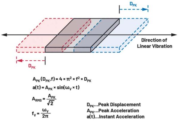
When measuring vibrations, it is important to understand the relationship between acceleration, velocity, and displacement. If a vibration, measured on one axis, causes 250 nm of displacement while vibrating at 1 kHz, the generated peak acceleration will be APK (250 nm, 1 kHz) = 1 g. For the same displacement at 10 kHz, the peak acceleration will now be APK (250 nm, 10 kHz) = 100 g.
It is vitally important to understand the potential vibrations that can occur in your asset before selecting a vibration sensor. Some motor manufacturers will provide such information. There are also some standards such as ISO 10816 that can help with this, as discussed in the “Noise Density” section.
When selecting a MEMS accelerometer for use with a machine covered under ISO 10816, we can follow some easy steps to determine if the g-range is acceptable for use. Equation 4 presents a specific example, which determines that measuring unacceptable vibration severity on a Class IV asset, per ISO 10816-1 (VMAX= 28 mm/sec), at a frequency of 1000 Hz (fMAX) will require a measurement good vibration severity levels and g-range to detect potential faults per class of motor. The only sensor that has sufficient noise performance and g-range is the range of at least ±25.3 g.4
It should be noted that these fault classes do not consider a MEMS sensor’s ability to withstand base load vibration. Typically, a sensor with a smaller g-range or full-scale range will be less resistant to wear and tear of its mechanical elements. Also, with a smaller full-scale range it is easier for vibrations of interest to be masked by baseline vibrations.
Table 8 shows ISO 10816 vibration severity charts both in mm/s and g for each class of asset. A range of MEMS accelerometers suitable for use in CbM applications are compared. ±16 g of g-range is not enough for use on Class III and Class IV assets, but it is acceptable for Class I and Class II. The only two sensors with sufficient g-range are ADXL1002 and MEMS C2.
| Peak Acceleration (g) | |||||
| g-Range | Class I 7.1 mm/s 6.4 g |
Class II 11.2 mm/s 10.1 g |
Class III 18 mm/s 16.3 g |
Class IV 28 mm/s 25.3 g |
|
| ADXL1002 | 50 g | Pass | Pass | Pass | Pass |
| ADXL317 | 16 g | Pass | Pass | Fail | Fail |
| MEMS B | 16 g | Pass | Pass | Fail | Fail |
| MEMS C1 | 16 g | Pass | Pass | Fail | Fail |
| MEMS C2 | 64 g | Pass | Pass | Pass | Pass |
Table 8. Comparison of MEMS Accelerometer g-Range for Use with Class I through Class IV Motors
Low g-range MEMS accelerometers for CbM (<±16 g) are limited to use on Class I and Class II machines, per ISO 10816, as the maximum vibration severity for Class III and Class IV machines exceeds ±16 g. This means that noise performance in low g-range MEMS accelerometers for CbM becomes even more important to ensure they can be used on Class I and Class II machines, as discussed in the “Noise Density” section.
When selecting a MEMS accelerometer for use in CbM applications, you must refer to the asset manufacturer’s specifications to find potential fault vibration severity information, perform your own tests, and/or refer to standards such as ISO 10816. By combining the information from Table 7 and Table 8, it is clear that the majority of CbM MEMS accelerometers on the market fail to meet the criteria outlined in ISO 10816 in terms of noise performance to measure known good vibration severity levels and g-range to detect potential faults per class of motor. The only sensor that has sufficient noise performance and g-range is the ADXL1002, one of a family of sensors from Analog Devices designed specifically for CbM applications. It is very clear that the current state of the art in MEMS accelerometers for CbM need to be classified based on this evidence, and this is shown in Table 9. Noise and bandwidth are considered the highest importance, hence the weighting. g-range is next, followed by temperature range and cross-axis sensitivity.
| Parameter [weight] | ADXL1002 | ADXL317 | Other MEMS Vendors |
||
| ±3 dB Bandwidth [5] | 1 | 5 | 3 | 4 | 2 |
| Noise Density [4] | 1 | 2 | 3 | 4 | 5 |
| g-Range [3] | 2 | 3 | 3 | 3 | 1 |
| Temperature Range [2] | 1 | 1 | 2 | 2 | 2 |
| Cross-Axis Sensitivity [1] | 1 | 1 | 3 | 2 | 2 |
| Total | 18 | 45 | 43 | 51 | 42 |
| Rank | First | Fourth | Third | Fifth | Second |
Table 9. Decision Matrix for Choosing the Best MEMS Accelerometer for PdM Based on Key Criteria
ADXL1002 is a clear leader in terms of performance and so is classified as the highest performance MEMS accelerometer in CbM applications. All other sensors, while still offering excellent performance, are classified as medium performance CbM accelerometers given the gaps in performance.
Temperature
There are several specifications to consider when it comes to temperature performance of MEMS accelerometers. Table 10 shows some very interesting comparisons between key temperature related data sheet specifications. Clearly there is a significant range in terms of the numbers, but what does this translate to in terms of performance? A review of the most common applications for CbM (oil and gas, metal processing, food and beverage, and power generation) shows that potential temperatures on assets can easily exceed 105°C due to factors, such as overdriving the load capabilities, leading to excess current being drawn, contamination (dust, debris) raising the internal temperature of a motor and preventing it from cooling, and even creating vibrations that can generate excess heat. External factors, such as potential gas or steam leaks, can also play a part in selecting a sensor. Piezoelectric manufacturers appear to favor a maximum temperature range of 120°C for most of their general-purpose vibration sensors with some application specific sensors having 150°C maximum operating temperature. A survey of high frequency sensors (up to 10 kHz and greater) showed that 74% of sensors had a maximum operating temperature range below 125°C, with 24% below or equal to 80°C. There are some special-purpose piezoelectric sensors that can withstand 200°C and higher just like there are special-purpose MEMS accelerometers that can work up to 175°C, but this article is not focused on sensors for very specific applications.
| ADXL1002 | ADXL317 | Other MEMS Vendors | |
| Temperature Range | –40°C to +125°C | –40°C to +125°C | –40°C to +105°C |
| Sensitivity Change | ±5% | ±2.5% (x, y) ±4.5% (z) | ±1% to ±4.35% |
| 0 g Bias Error | ±10% | ±9% | ±0.1% to ±1% |
Table 10. Temperature Performance Comparison of MEMS Accelerometers for CbM
Sensitivity defines the amount of output change per unit of acceleration. Sensitivity change over temperature defines how the sensor’s sensitivity changes over temperature. It is not uncommon to see piezoelectric accelerometers with scale factor error over temperature up to 20%, which could lead to significant drift, although 5% is more typical. Such errors require calibration during production. MEMS accelerometer scale factor or sensitivity error over temperature is excellent due to being trimmed electrically during production, resulting in sensors that do not drift over temperature. As an example, if the ADXL1002 was exposed to a temperature change from 25°C to 85°C, the sensitivity (40 mV/g) would change by 0.03%/°C × 60 = 1.8%, which means the sensitivity change over 60°C is within 39.28 mV/g to 40.72 mV/g. This shows that for MEMS accelerometers the sensitivity is quite stable vs. temperature change. For most applications, temperature compensation for sensitivity is not required.
Zero g offset is the output of the accelerometer when no acceleration is applied. Ideally this should be zero, but due to inherent imperfections within the MEMS sensor we see a dc offset. In most cases, maintenance professionals are primarily concerned with dynamic data (ac output from the accelerometer) such as deviations from baselines or trending away from an operating normal. For this reason, zero g offset is not a prime concern when using MEMS accelerometers for CbM. Zero g offset can be easily calibrated out of measurements, and most high performance digital sensors will provide registers to perform this action with ease. Where dc or tilt detection is of interest, zero g offset over temperature can also be calibrated out. The smaller the operating temperature range, the easier this will be.
Number of Axes
MEMS accelerometers are available in single, dual, and triaxial versions. Unlike piezoelectric accelerometers, there is no real size difference between single and triaxial MEMS accelerometers. Smaller size is one of the key advantages of MEMS over piezoelectric, along with much lower power consumption and higher levels of integration. With 3-axis piezoelectric accelerometers there are some clear disadvantages—such as cost, which can be up to three orders of magnitude higher compared to triaxial MEMS accelerometers, size, and accuracy—but one of the main drivers for using triaxial piezoelectric accelerometers is to allow easier collection of data for portable vibration readers. Instead of having to prepare three sites (single-axis sensors) then take three separate readings, one triaxial sensor can do this alone. For assets with restricted access, this can be a major advantage. Also, when measuring vibrations in multiple directions, it can be important to maintain phase relations between axes and a triaxial device will ensure this. For complex vibration analysis it is important to see events on all axes with no phase mismatch as this could lead to misinterpretation of events.
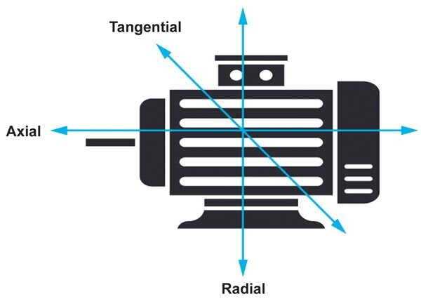
With a triaxial piezoelectric sensor measuring vibration in the x, y, and z directions it is possible to measure the tangential motion/vibration of the axis of rotation. Many mechanical forces generated by rotating machines—soft footing, for example—produce such tangential motions of the casing. This is not possible to detect with a single-axis piezoelectric sensor. With single-axis MEMS accelerometers, it may be possible to detect such events because the dc content of the measured signal corresponds to tilt, assuming the resulting rocking of the asset occurs in the sensitive axis.
Vibration excitation is often directional, depending on the fault, such as a spall on an outer bearing race, mechanical looseness, misalignment, or a bad gear tooth. The direction of the fault vibration is not always predictable, so one can’t know which direction—axial, radial, or tangential—the vibration will travel. There also can be more than one fault causing abnormal vibrations. One study focused on demonstrating the potential for improved diagnostic capability when using triaxial piezoelectric sensors vs. single axis radial and axial sensors.6 The study revealed that single-axis accelerometers can miss the diagnosis of nearly 50% of the mechanical faults outlined previously if sensors are only placed radially or tangentially as shown in Figure 4. Seeing as the direction of the fault vibration is the issue, adding more sensors on the same axis will not solve this problem. Adding an axial accelerometer improved fault detection to almost 70%. Adding one more axial sensor increased the detection to 80%. This shows that the extra diagnostic information from different axes can lead to better fault detection, but not that this must be done with a triaxial sensor. This study found that having data for all three axes was redundant in many cases but still recommended measuring on three axes if possible.
While having more data is always beneficial, it is not always required, especially in wireless systems where measuring or transmitting redundant data can shorten the life of the battery. Proper placement of sensors whether they be single, dual, or triaxial is critical but according to the above research, based on wired piezoelectric sensors, triaxial sensors should be used whenever possible.
For MEMS accelerometers, any existing triaxial sensors have reduced performance compared to piezoelectric sensors, so the likelihood is that they will not be able to detect as many faults. Furthermore, the z-axis in most triaxial MEMS accelerometers has lower performance in noise, bandwidth, or both, as shown in Table 11, possibly weakening the potential added value of extra axes reported by studies based on triaxial piezoelectric accelerometers. In some cases, all axes will have different performance in terms of noise and/or bandwidth, the two most important specifications for CbM.
| ADXL1002 | ADXL317 | Other MEMS Vendors | |
| Bandwidth X | 11 kHz | 4 kHz | 4.2 kHz to 8.2 kHz |
| Bandwidth Y | 4 kHz | 4.2 kHz to 8.5 kHz | |
| Bandwidth Z | 2 kHz | 2.9 kHz to 6.3 kHz | |
| Noise X | 25 µg/√Hz | 55 µg/√Hz | 75 µg/√Hz to 300 µg/√Hz |
| Noise Y | 55 µg/√Hz | 75 µg/√Hz to 300 µg/√Hz | |
| Noise Z | 120 µg/√Hz | 110 µg/√Hz to 300 µg/√Hz |
Table 11. Variation in Noise and Bandwidth from Axis to Axis for MEMS Accelerometers for CbM
The implications of this mismatch in terms of noise and/or bandwidth performance first appears to somewhat negate the advantages of having extra axes (y, z) in one place on an asset. This is well understood by designers familiar with MEMS sensors, but a few things need to be considered. MEMS triaxial accelerometers can be orders of magnitude lower in cost with comparable performance to piezoelectric accelerometers and far smaller, so more sensors can be placed, even in wireless installations on less critical assets. This provides more diagnostic insights into the general operation of the asset.
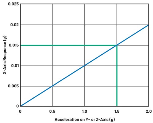
Figure 5. Cross-axis sensitivity observed on the x-axis of a 3-axis accelerometer accelerating in y or z axes.
Cross-Axis Sensitivity
Cross-axis sensitivity (CAS) refers to how much output is seen on one axis when acceleration is imposed on a different axis, typically expressed as a percentage. For piezoelectric accelerometers, which are predominantly single axis, this will be given as transverse sensitivity, which describes the sensitivity to any motion not on the same axis it was designed to measure on. For a triaxial accelerometer experiencing acceleration only on its y-axis, some acceleration will be measured on the x and z axes due to CAS. Figure 5 shows a CAS of 1% as the y (or z) axis experiences 1.5 g of acceleration; this is also observed on the x-axis as 15 mg or 1% of 1.5 g. This phenomenon also affects single-axis MEMS accelerometers. The lower this percentage, the more accurate and reliable is the vibration data that can be measured and used to detect faults, anomalies, and drifting trend lines.
Some MEMS manufacturers leave critical information like CAS off their data sheets, as shown in Table 12, but for CbM and PdM this is a vital specification that must be understood when trying to detect failures early where they are likely to be close to the noise floor of the sensor. The 1% listed for the ADXL1002 could be considered conservative as tests have shown performance to be slightly better.
| ADXL1002 | ADXL317 | Other MEMS Vendors | |
| Cross-Axis Sensitivity | 1% | 1% | Not listed, or up to 2% |
Table 12. Cross-Axis Sensitivity Comparison for MEMS Accelerometers Used in CbM
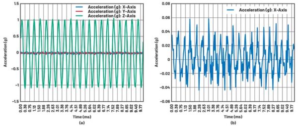
Figure 6a shows a CAS test on a MEMS accelerometer. Vibration was applied in the z-axis only. Figure 6a shows the z-axis measured an acceleration of approximately 1.1 g peak, whereas the x-axis in Figure 6b measured approximately 0.05 g peak acceleration and the y-axis slightly less at 0.0425 g.
Table 13 shows the worst-case CAS of 2.6% on the x-axis and 2.2% on the y-axis. There could be misalignments in the test setup, so the likelihood is the CAS is at least 2% but below 2.6%. While it is possible to calibrate CAS, it is desirable to have this value close to 1%, which is the industry-leading value for MEMS CbM accelerometers. Piezoelectric CAS is typically around 5%, but, in some cases, up to 15% is reported.7 Transverse sensitivity values below 5% are available on request from some piezoelectric vendors at an extra cost.
| Acceleration Peak (g) |
Acceleration RMS (g) |
CAS % (RMS) |
|
| Z-Axis | 1.1 | 0.76 | |
| Y-Axis | 0.0425 | 0.017 | 2.2 |
| X-Axis | 0.05 | 0.02 | 2.6 |
Table 13. MEMS B Sensor Cross-Axis Sensitivity
Solutions for Mechanically Attaching MEMS Sensors to Machines
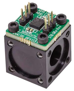
Figure 7: Mechanically optimized mounting block for accelerometer breakout boards (EVAL-XLMOUNT1).
Piezoelectric accelerometers are the vibration sensors most commonly used today. They have standard interfaces like IEPE and 4 mA to 20 mA, as well as various mounting methods like stud, magnet, and adhesive. For MEMS accelerometers to compete with the long-standing gold standard for vibration sensing, it is imperative to not only match their performance but to make it easy to attach MEMS sensors to assets. This has been a pain point for MEMS accelerometer customers for some time now. Multiple resonances will exist in any vibration measurement setup, and it is important to minimize their effect on measurements. Above 1 kHz bandwidth, mounting becomes critical as resonances can affect measurements significantly.
For piezoelectric accelerometers, there are a myriad of mounting strategies with stud mount offering the widest frequency response all the way down to handheld probe tips with the lowest frequency response range. MEMS accelerometers do not have a susceptibility to magnets and can and have been used successfully with magnetic mounting strategies.
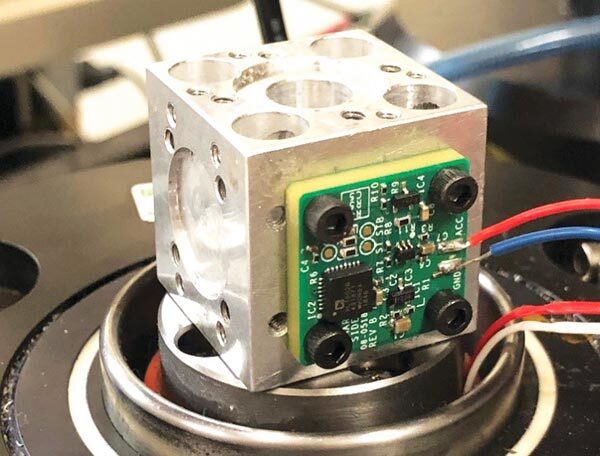
In order to make it easy to mount MEMS sensors to assets, Analog Devices created a mounting cube as shown in Figure 7. A central mounting hole with a diameter of 0.2 in. and a surrounding lip of 0.38 in., which is 0.3 in. deep, allows for a #10 machine screw to be used for fixing the mounting block to the asset. Breakout boards for multiple accelerometer families (EVAL-ADXL100XZ, EVAL-ADXL35XZ, and EVAL-ADXL37XZ) are compatible with this mechanical mount. By using this mounting block and fixing it securely to the mechanical source, the accelerometer frequency response can be evaluated in a controlled environment.
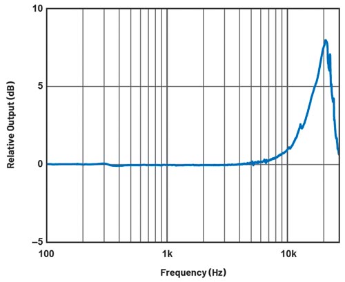
The mounting fidelity of the accelerometer is critical when capturing high frequency events. This was verified on a vibration shaker table and is shown in Figure 8 with the resulting frequency response shown in Figure 9.
The sensor PCB was designed a little thicker (3 mm), and specific solder paste was used to aid in preserving the data sheet frequency response of the MEMS sensor while mounted to an asset.
The reference design PCB shown in Figure 8 converts MEMS accelerometer data to IEPE format. It powers the MEMS accelerometer from an existing IEPE setup and outputs data in IEPE format, allowing seamless and simple integration of MEMS accelerometers into new or existing IEPE infrastructure.
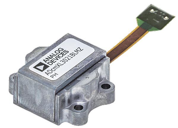
Analog Devices has a long history of integrating industry-leading sensors, signal conditioning, and processing into modules. The latest CbM modules are ADcmXL1021 and ADcmXL3021, single or triaxial (1× or 3× ADXL1002) accelerometer-based SPI output solutions capable of being mounted directly to assets. They have a mechanical package resonance above 50 kHz, well above the bandwidth of interest at 10 kHz.
The mounting holes accept M2.5 screws to hold the module in place. Stainless steel screws torqued to about 25 inch-pounds are used for many of the characterization curves shown in the ADcmXL3021 data sheet. In some cases, when permanent mounting is an option, industrial epoxies or adhesives, such as cyanoacrylate adhesive, in addition to the mounting screws, can be used to enhance mechanical coupling.
We have already seen that ADXL100x MEMS accelerometers have similar levels of performance as piezoelectric accelerometers, with several distinct advantages that are now enabling CbM and PdM to be applied to less critical assets. At the same time, the ADXL100x family of MEMS accelerometers, shown in Table 14, are being installed on highly critical assets, which is unprecedented for MEMS accelerometers. At Analog Devices, we’ve made it simple to attach our CbM sensors to assets (XLMOUNT1, ADcmXL3021). It is also very easy to replace piezoelectric sensors with MEMS due to our conversion reference designs (MEMS to IEPE or 4 mA to 20 mA).
| Part Number | Number of Axes |
Accelerometer Range |
Noise Density (typical) g/√Hz |
BW (typical) Hz |
Is (typical) A |
Vs+ (min) V |
Vs+ (max) V |
| ADXL1001 | 1 | 100 g | 0.00003 | 11,000 | 0.001 | 3.3 | 5.25 |
| ADXL1002 | 1 | 50 g | 0.000025 | 11,000 | 0.001 | 3.3 | 5.25 |
| ADXL1003 | 1 | 200 g | 0.000045 | 15,000 | 0.001 | 3 | 5.5 |
| ADXL1004 | 1 | 500 g | 0.000125 | 24,000 | 0.001 | 3.3 | 5.25 |
| ADXL1005 | 1 | 100 g | 0.000075 | 23,000 | 0.001 | 3 | 5.25 |
Table 14. ADXL100x Family of CbM Accelerometers
Our CbM reference designs, evaluation systems, development platforms, and system solutions are all aimed at enabling our customers to develop the best CbM and PdM systems to keep assets and factories running. We have addressed and solved most of the pain points experienced by CbM designers using not only MEMS but piezoelectric accelerometers too, and we will continue to invest in industry-leading CbM solutions. The next section discusses one such example of a high fidelity, high speed data acquisition pipeline that enables CbM system developers to detect and save vital vibration data into their machine learning development environment (Python, TensorFlow, MathWorks, etc.).
CbM Development Platform
The CN-0549 CbM Development Platform, shown in Figure 11, brings together all the MEMS design considerations outlined above to offer the highest performance MEMS accelerometer for CbM that can be mounted to an asset with ease while maintaining data sheet performance. The data acquisition board provides a high speed, 24-bit resolution signal conditioning and data acquisition hardware solution for use with IEPE piezoelectric and MEMS accelerometers. Also provided is all the necessary firmware and evaluation software to run this system out of the box.
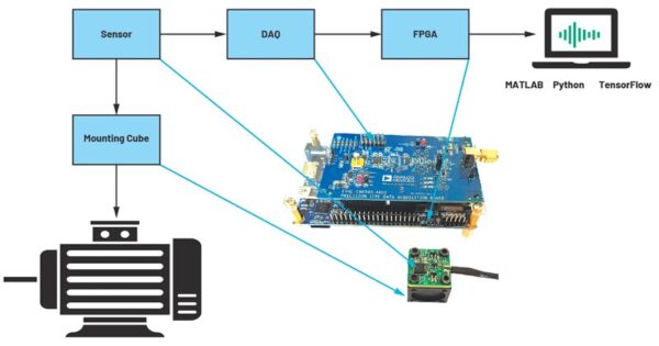
Figure 11: CN-0549 block diagram and image.
The CbM Development Platform is targeted at enabling CbM designers to collect large amounts of high quality vibration data in order to understand their asset’s operating behavior. Once this is understood, faults can be seeded or simulated in order to develop trending information to allow the machine learning algorithms to identify and profile a potential fault. This fault data must be captured with the highest fidelity and streamed to a machine learning environment to develop models to better understand the asset’s behavior.
The CbM Development Platform enables streaming of high performance IEPE vibration sensor data to a machine learning environment, such as TensorFlow, out of the box. A multitude of IEPE piezoelectric sensors (note these will not require the mounting cube to attach to an asset) or the ADXL1002 IEPE solution, CN-0532, can be used with the CbM Development Platform. The DAQ board, CN-0540, another reference design providing the highest precision data acquisition signal chain for IEPE sensors, provides a full bandwidth data pipeline into the FPGA where the system can monitor the data profile of the machine. An oscilloscope application, running on the FPGA, requiring only a connection to a monitor via HDMI®, provides frequency spectrum information and allows users to quickly visualize their machine’s health or to stream data to the cloud over Ethernet. Python and MATLAB® bindings enable designers to directly interface the machine learning data into these popular tools. Designers can then take their machine learning data and start creating algorithms for their equipment to improve maintenance strategies, as well as predict failures and potential factory downtimes.
Conclusion
This article discussed the most important criteria to be considered when using MEMS accelerometers in CbM systems. It was shown that a small number of MEMS accelerometers can offer a viable alternative to piezoelectric accelerometers; however, significant gaps in performance were highlighted amongst MEMS accelerometers, outlining the requirement for a classification of these sensors. These were discussed and compared against existing ISO 10816 vibration standards, further identifying the difference in performance of MEMS sensors for CbM.
MEMS sensors were classified according to the most important specifications, such as noise, bandwidth, g-range, and more. Due to their wide bandwidth, ultralow noise, and high g-range, the ADXL100x family of sensors are clearly the only sensors capable of competing with piezoelectric accelerometers and, having been extensively compared to the MEMS competition, can be considered the only high performance MEMS sensors available today for CbM and PdM applications. In the medium performance category, which is where all other MEMS CbM sensors reside, Analog Devices offers a wide range of triaxial, digital sensors like ADXL317, one of the lowest noise, wide bandwidth digital MEMS accelerometers capable of detecting vibrations early and helping to keep assets and even factories running.
For more information on CbM sensors to CbM solutions, please visit analog.com/CbM.
References
1 “Motor Monitoring Market by Offering (Hardware, Software), Monitoring Process (Online, Portable), Deployment, Industry (Oil and Gas, Power Generation, Metals and Mining, Water and Wastewater, Automotive), and Region—Global Forecast to 2023.” Research and Markets, February 2019.
2 Chris Murphy. “Choosing the Most Suitable Predictive Maintenance Sensor.” Analog Devices, Inc., June 2020.
3 Pete Sopcik and Dara O’Sullivan. “How Sensor Performance Enables Condition-Based Monitoring Solutions.” Analog Dialogue, Vol. 53, No. 2. June 2019.
4 Mark Looney. “MEMS Vibration Sensing: Velocity to Acceleration.” Analog Devices, Inc., March 2017.
5 Mark Looney. “MEMS Vibration Monitoring: From Acceleration to Velocity.” Analog Devices, Inc., June 2017.
6 William Watts. “Triaxial Vibration Spectral Data: An Important Ingredient for Proper Machine Diagnostics.” Azima, DLI, 2009.
7 “Understanding the Role of Transverse Sensitivity in Measurement Data Reliability.” Endevco.
Author
Chris Murphy,
About the Author: Chris Murphy is an applications engineer with the European Centralized Applications Center, based in Dublin, Ireland. He has worked for Analog Devices since 2012, providing design support on motor control and industrial automation products. He holds an M.Eng. in electronics by research and a B.Eng. in computer engineering. He can be reached at christopher.murphy@analog.com.
Visit: https://ez.analog.com
Contact Romania:
Email: inforomania@arroweurope.com
Mobil: +40 731 016 104
Arrow Electronics | https://www.arrow.com


