


Just five years ago, ‘digital power’ remained a hazy concept for the great majority of the engineering community. Even the term held meanings that could demand clarification, as digitally aware power-management ICs were well accepted while the latest digital power-converter solutions struggled to penetrate mainstream consciousness. In 2008, the first modular digital power converter arrived to revamp the quarter-brick format, beating the best-developed analog modules.
Author: Patrick Le Fèvre, Marketing and Communication Director at Ericsson Power Modules
Complementary parts have quickly completed the industry’s first family of modular digital power-converters, so expectations have run high for the explosive growth that the digital revolution has stimulated elsewhere. But to date, uptake for the digital power sector overall has been firm rather than explosive, despite first-generation modular solutions being at least equal and typically outstripping the key performance metrics of highly developed analog counterparts. Importantly for product designers, off-the-shelf digital power-converter modules enable matchless opportunities for new design without spending endless hours in power supply studies.
What’s wrong with analog?
It is worth remembering that ‘digital power’ is something of a misnomer – much of a digital power supply mirrors analog practice and uses similar or identical components in key areas such as the power switches and output filter. Also, digital power-supply controllers are almost certain to exploit mixed-signal construction rather than commodity logic bulk CMOS. Fundamentally, only the inner control loop changes to implement digital’s flexible methodology, with the PMBus™ measurement-&-control subsystem representing a crucial adjunct that adds little to component cost, yet hugely influences future outcomes.
So, what are analog’s shortcomings that justify a new approach and working methods? The answer is of course a combination of factors with conversion efficiency often highest on the list. Campaigns between competitive products are increasingly becoming inseparable apart from a banner statistic of ever-decreasing magnitude. Clearly, a 1% improvement in any application is worthwhile, but it is the recognition of impending product maturity that explains Ericsson’s decision in 2006 to a blue-sky project that explored digital power conversion. Following two years of intensive effort that included inventing software tools to ease firmware development, 2008 saw the release of the BMR453 advanced intermediate bus converter (IBC), followed by the BMR456 in 2012, which embedded the Ericsson DC/DC Energy Optimization firmware. This new product doubled the power density of a tightly regulated bus converter and also bettered key efficiency and regulation performance parameters.
For instance, under normal operating conditions the efficiency metric rose slightly to 96% or more within the 50 to 70% of full load area that is the traditional sweet spot for analog converters. Unlike a regular analog converter, digital converters can adapt to changes in line and load conditions in real time, as the new converter demonstrated by flattening the efficiency graph to extend similar performance toward the 10% low-load area that seriously challenges analog converters. This is significant because along with ‘permanently-on’ consumer goods such as set-top boxes, systems large and small increasingly shut down circuits that are not needed to support throughput during periods of low demand to save on energy bills.
These savings can be maximized via the use of intermediate bus and similar architectures by backing off the bus converter’s output voltage to minimize dissipation in the point-of-load regulators during low-load periods. This dynamic bus voltage regulation technique is straightforward to implement using digital converters that feature comprehensive PMBus measurement and control capabilities. Apart from an on/off control via a hardware input, analog converters use voltage levels to influence internal circuitry, typically constraining functionality to output-voltage trims.
Accessibility
A typical digital converter that implements the PMBus offers an array of control options that are bewildering at first sight. As a result, one modular power vendor has taken to promoting products that omit the terminals needed for PMBus connectivity in the interests of easing customers’ conversion to digital power. Ericsson does the same, but only to minimize cost in applications that will never benefit from PMBus or be useful as an evaluation exercise using hardware whose performance characteristics are well known. Yet this approach highlights two cornerstone requirements that are embedded within the PMBus protocols:
• Any PMBus-compliant device must be capable of powering up and working seamlessly without the need for digital connectivity or programming (i.e. in stand-alone mode)
• When programmed, the device shall retain its configuration data indefinitely or until it is next programmed (the ‘set-&-forget’ facility).
These features make it easy to employ digital converters as upgrades for obsolescent analog parts, delivering efficiency improvements and a feature set that can be precisely tailored to a particular part’s role within the design: output voltage, power up/down delays and fault thresholds are common examples. The engineer does not have to program off-the-shelf parts that arrive suitably configured; this work has been done at the chipmaker’s facility. If changes are necessary at a later stage, it is easy to accomplish them using low-cost tools that replicate the functionality that is familiar from working with other programmable logic devices.
Similarly, in-circuit programming is possible if an access route exists, which is sufficient reason for including PMBus connections every time the possibility exists.
Because programmability is a key feature of PMBus, our connector-less vendor retains the capability through the artifice of three special-purpose connections.
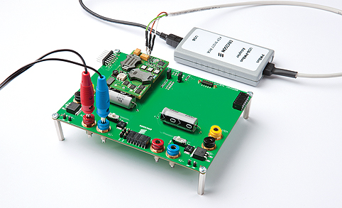
These consist of the same serial bus connections that appear on any PMBus connector and echo original design exercises at Ericsson, as Figure 1 shows for the USB-to-PMBus adapter with a BMR453 advanced bus converter.
Users who do not want PMBus do not have to use it, and would better advised to retain the conventional format and connect the bus to a header. This avoids the user maintaining different PCB library footprints and leaves the door open for programming and monitoring the part during development through to a repair technician’s visit, or any time that a PMBus connection is available. It also provides a platform for designers to accumulate real-time experience that is likely to stimulate product improvements.
The smart way to make digital power conversion and PMBus control approachable is to acquire a development kit in the same way as for any other programmable device or system. Assuming normal bench test equipment, what is required is at least one test board to accommodate the product line of interest, product samples, a PC-to-PMBus adapter and development software.
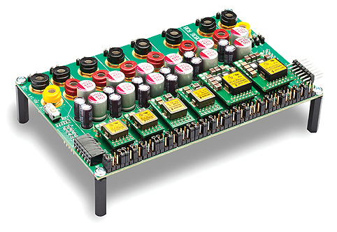
These elements appear in purpose-built products that Ericsson constructs to withstand representative current levels, such as the six point-of-load regulator board, shown in figure 2.
The connectors that daisy-chain PMBus connections between assemblies are visible at each end with additional boards allowing configurations that can replicate many systems. Engineering support includes the industry’s greatest depth of literature in support of digital power conversion – and one that is freely available to all.
The latest development software to become available is Ericsson Power Designer, which can be downloaded for free and run without target hardware to gain an impression of its capabilities. In common with its vendor’s earlier software packages, the initially daunting PMBus command language soon becomes the friend that was intended by its designers. Standard commands occupy one byte whose value is most often arbitrary thanks to English-like names that are divided into functional groups, as can be seen by downloading the specifications for free.
Fears that it is necessary to understand the mechanics of digital signal processing soon give way to appreciating the rationale behind an elegant working methodology that simplifies design processes by rationalization that is applicable across the gamut of application complexity.
For instance, if an application justifies visiting the complexities of proportional-integral-differential (PID) control, the user can access and configure the constants that determine a converter’s inner-loop behavior to fine-tune transient response performance for a given set of load conditions.
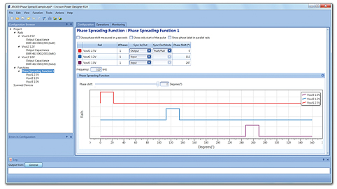
As always, a common-sense approach works best, founded upon starting simple, and peripheral features of the digital workflow that encourage recording a project’s progress highlight their value when experimenting to build confidence as well as during a real project. An example is synchronizing multiple converters for EMC control purposes or to enable current sharing between converters in parallel without needing steering diodes, as figure 3 shows.
Working in harmony with the in-built capabilities on offer from today’s digital converters, it is easy to implement tasks using PMBus commands that truly challenge analog converters.
For more information, please visit www.ericsson.com/powermodules