


When faced with the decision of what to use for the clock source in an electronic design, the traditional assumption has been that the only realistic choice for any application that needs even moderate accuracy is a quartz-based oscillator.
Author: Craig Bakke, Product Manager at Digi-Key
Quartz has dominated the market for decades but its limitations are opening up opportunities for new technologies. Quartz oscillators rely on the material’s piezoelectric properties. The crystal distorts when a electrical pulse is applied to it. Conversely, its distortion leads to the generation of an electrical signal. These two aspects of the piezoelectric effect are used in oscillators to induce resonance such that the crystals oscillate within a narrow range of frequencies. The key to controlling the frequency and range of frequencies lies in size and shape of the crystal. The higher the desired frequency, the smaller the crystal, but as the crystals are made smaller they become more fragile and harder to make reliably.
Maintaining tight frequency control involves the use of a number of external components and often leads to precise rules over how the devices are placed on a board and how close they can be to other parts of the system.
To provide a stable clock signal, the oscillator circuitry needs to be protected from onboard interference. High-frequency data buses can inject switching noise into the oscillator feedback loop, disturbing the relatively weak signal produced by the quartz crystal. In general, the simplest way to protect the oscillator is to keep most signal traces and components outside an ‘exclusion zone’ of several square centimetres on the PCB.
One issue that quartz clocks face is frequency shifting caused by the high temperatures encountered during soldering. Crystal-based products exposed to solder reflow, during which temperature excursions may reach more than 200°C for tens of seconds, can experience frequency shifts of up to ±5ppm.
Quartz devices are also vulnerable to shock and vibration because of the way in which the crystal needs to be held within the package. As a result, the trend for miniaturisation in electronics as well as demand for more rugged devices is building demand for other options.
Silicon semiconductor technology has moved into the position where it can provide an effective alternative. Microelectromechanical machine (MEMS) technology provides one way to harness semiconductor-grade silicon for clock generation, with an increasing number of products arriving on the market based on this approach.
The core component of the MEMS clock generator is a mechanical resonator etched from a silicon wafer, tuned to vibrate at a target frequency. Masses of various sizes and shapes, including discs and multibeam structures, have been used to create the vibrating element, which is generally set into motion using electrostatic interactions. The mass of this resonator is extremely small – often on the order of one ten-billionth of a gram. The small mass can be used to generate high frequencies that often require cuts to quartz crystals that are difficult and expensive to make.
The MEMS resonator can be constructed using a variety of silicon-based materials, such as single-crystal silicon, polysilicon or polysilicon-germanium (poly-SiGe). The resonators are susceptible to the adsorption of moisture. A single layer of water can push the operating frequency down by hundreds of parts per million as the mass of the resonator increases. To prevent adsorption, MEMS timing devices need to be sealed against the environment.
Their resonating frequencies will also drift significantly with temperature – the materials become softer as temperatures rise leading to a temperature coefficient of up to −40 ppm/°C.
However, MEMS products are typically less vulnerable to temperature shifts caused by reflow soldering. For example, Maxim Integrated’s MEMS-based real-time clock products experience a shift of less than ±1ppm following reflow, five times lower than equivalent quartz products. Being much smaller, MEMS products exhibit much greater immunity to shock and vibration than quartz-based components.
To deal with the problem of temperature-related frequency shifts, the output of the MEMS resonator is typically compensated electronically. This can be done in a similar manner to the techniques used for temperature-compensated crystal oscillators (TCXOs). One digital technique is to provide an electronic reference oscillator, based on a transimpedance amplifier, that is fed to a fractional-N synthesiser and phase-locked loop. The output of the reference oscillator is measured during calibration at room temperature and compared to the target frequency. The output is then measured at another temperature and these results stored in local memory.
As temperature shift is normally monotonic, only a few points are needed to provide voltage offsets that are used to drive the frequency synthesiser or PLL to provide the required frequency output.
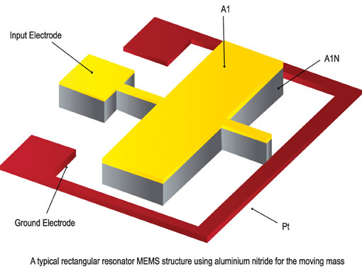
To improve the performance of MEMS resonators, aspects of quartz and MEMS have been brought together, using piezoelectric effects rather than mechanical resonance. IDT, for example, manufactures piezoelectric MEMS-based oscillators. In these devices, the cantilevered beam is coated with a thin piezoelectric film made from materials such as aluminium nitride or zinc oxide.
The combination of structures leads to strong electromechanical coupling, providing low resistance motion and high quality factors, or resonance. Vendors claim the structure leads to high long-term frequency stability and low jitter. For example, the IDT pMEMS products offer sub-picosecond jitter with products operating at up to 20MHz.
To support use in high-frequency communications, networking and computing designs – which need sources in the 150MHz to 200MHz range – IDT took advantage of its ability to copackage the tiny MEMS resonators with signal-conditioning circuitry to provided its pMEMS products with low-voltage differential signalling (LVDS) and low-voltage positive emitter-coupled logic (LVPECL) outputs.
As well as providing an alternative to quartz, MEMS technology is also creating new opportunities for the piezoelectric material.
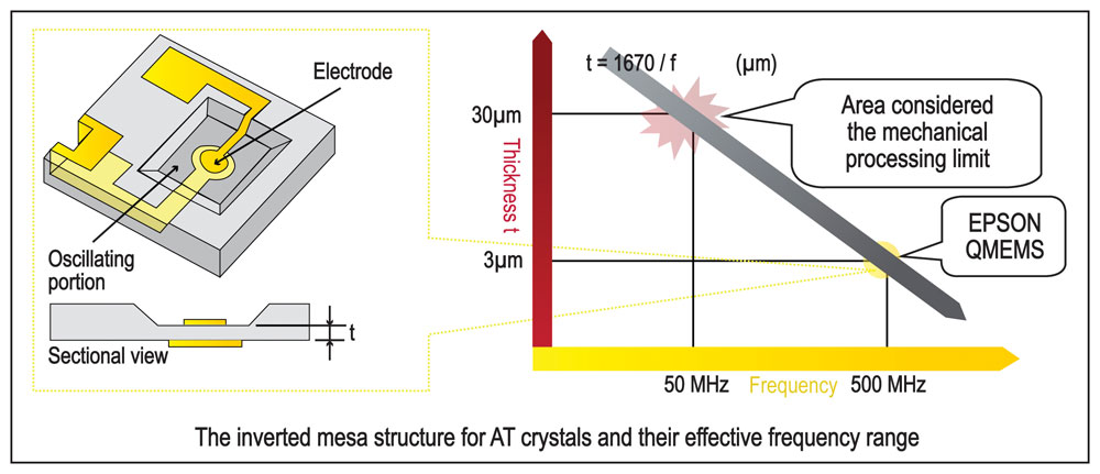
To provide greater control over frequency, Epson-Toyocom started to use micromachining techniques on quartz and developed the QMEMS range of devices to create new shapes such as the inverted-mesa – a sunken structure with steep walls and a flat bottom within a larger quartz crystal that is placed closed to the excitation electrodes. This shape allows operation at higher frequencies as it reduces the thickness of the oscillating portion of the crystal to just a few micrometres. The larger surrounding area is left as a support to maintain overall mechanical strength. The use of a thinner oscillating section also reduces the sensitivity of the device to frequency dips and thermal changes.
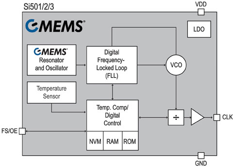
One promise of MEMS is to facilitate high integration. In principle, the resonator structure can be integrated onto the same die as the compensation and other signal-conditioning circuitry. In practice, cost and yield considerations mean that many of the MEMS products on the market are two-die solutions. Silicon Laboratories has been able to combine MEMS and commercial CMOS with its Si50x series of products. Silicon Labs’ CMEMS is a technology that enables the post-processing of MEMS structures on a silicon CMOS wafer, using poly-SiGe as the MEMS structural material. It can be deposited at temperatures comparable to those used to produce the metal wiring on conventional CMOS ICs. That means the processes used to deposit the poly-SiGe will not melt the existing CMOS and backend materials if directly deposited on top of a mainstream CMOS wafer. The etching agents, which are used to cut away material from underneath the resonator so that it can vibrate are friendlier than the hydrofluoric acid and other etchants commonly often used in dedicated MEMS processes. To stabilise the frequency output, the Si50x CMEMS oscillators employ the DSPLL technology used in Silicon Labs’ crystal-based oscillator family for a total stability of as little as ±20ppm over ten years.
A further step is to move away from mechanical or piezoelectric resonators and to use an entirely electronic solution. Inductor-capacitor (LC) resonating circuits have been used as a relatively low-quality clock source for microcontrollers for some years, but their application has been limited because their jitter is on the order of tens of thousands of parts per million. Improvements to PLL technology applied to quartz and MEMS products has been used to tighten up the specification of electronic resonators, making them now usable in a much wider range of designs.
Because the parts are entirely electronic and their output controlled using data stored in a lookup table, they can be programmed in the factory to provide any required frequency within their output range.
Products such as Silicon Labs’ Si500, for example, can support any frequency between 900kHz and 200MHz with a total stability of ±150ppm. As they have no moving parts, the devices are practically impervious to shock and vibration effects and are unaffected by the heat generated during soldering.
Thanks to developments in silicon-processing technology, the quartz clock is no longer the only option for designers seeking high-performance timing solutions. Through the use of MEMS, hybrid-MEMS or fully electronic timing control, designers now have access to a widening range of devices that can meet cost, vibration and reliability targets ■
Digi-Key
www.digikey.com