


Capacitive-based encoders offer a combination of performance, reliability, and accuracy not available with traditional encoder technologies.
Author: Jeff Smoot, VP of Motion Control, CUI
Background
Rotary encoders provide critical information about the position of motor shafts and thus also their rotational direction, velocity, and acceleration. They are vital components in the motion-control feedback loop of industrial, robotic, aerospace, energy, and automation applications. In these installations, encoders are asked to provide long-term reliability, durability, and high performance despite often working in severe conditions that include dust, dirt, grease, fluctuating temperatures, and heavy vibration. The need for encoders has been increasing dramatically with the rise in applications requiring precise motion control.
The challenge for design engineers has been to choose between the tradeoffs of the two most-common encoder technologies: optical and magnetic. The optical approach offers the best accuracy but with reduced reliability; the magnetic approach provides greater durability but less accuracy. While some designs can avoid using encoders entirely, the reality is that encoders are a vital link in the overwhelming majority of control/feedback loops (see Sidebar #1, “What about sensorless designs?”).
Encoder technologies require tradeoffs
Standard encoders typically provide between 48 and 2048 pulses per revolution (ppr), with most applications requiring between 800 to 1024 ppr. While higher ppr may seem to offer greater apparent precision, it is both more costly and more complex, placing additional calculation and processing burdens on the system controller or digital processor that is closing the loop. In addition to being unnecessary, excess precision can actually be detrimental due to noise, vibration, and jitter in shaft position.
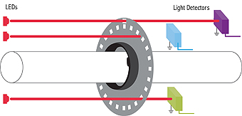
Most shaft encoders are based on optical or magnetic principles. The optical method uses a glass or plastic disk with two sets of windows around the periphery, Figure 1. A LED light source and photodetectors are located on opposing sides of the disk; as the disk turns, the on/off passing of light through the windows provides the typical square wave A & B quadrature pulses.
While used successfully, this optical approach has several drawbacks. With respect to ruggedness, factors such as dirt, oil and other containments, all of which occur both during assembly and also over time in the field, can easily interfere with the disk and slots, and thus the encoder output. The traditional approach to mitigate exposure to contaminants is to place the encoder in a bell housing. Unfortunately, this approach does not completely eliminate exposure to environmental contaminants. Additionally, it introduces new factors to the equation including elevated temperatures and higher application costs.
Further, the LEDs in optical encoders have a limited lifetime and their brightness can dim by half within 10,000 to 20,000 hours (roughly one to two years), and they eventually burn out. If the disk is made of plastic as a cost reduction measure, it will a have limited temperature range, and any distortions or warping will affect accuracy.
The magnetic encoder’s construction is similar to the optical encoder, except that it uses a magnetic field rather than beam of light. In place of the slotted optical wheel, it has a magnetized disk which spins over an array of magneto-resistive sensors. Any rotation of the wheel produces a response in these sensors, which goes to a signal-conditioning front-end circuit to determine shaft position. While it offers a high level of durability, the magnetic encoder is not as accurate and is highly susceptible to magnetic interference produced by electric motors, most notably stepper motors.
In addition to optical and magnetic encoders, Hall-effect sensors can be used for position encoding. While effective and reliable, they are suitable only for relatively low-accuracy/resolution determination of shaft position.
An innovative approach based on a proven design
Given the need for accurate, precise, and rugged rotary-position encoding, CUI looked for other electronic techniques which could be used. Their solution was to adapt the capacitive-sensing operating principles of a standard linear-position encoder, as developed for vernier calipers over 30 years ago (see Sidebar #2, “From caliper to encoder”). The result is a highly durable and accurate rotary encoder platform known as AMT.
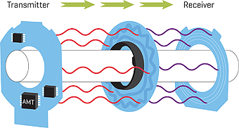
Capacitive sensing uses patterns of bars or lines, with one set on the fixed element and the other set on the moving element, to form a variable capacitor configured as a transmitter/receiver pairing, Figure 2. As the encoder rotates, an application specific integrated circuit (ASIC) counts the line changes and also interpolates to find the precise position of the encoder and direction of rotation.
By design, the encoder ASIC’s electrical output is 100% compatible with optical and magnetic encoders. This non-contact encoder implementation has several significant user benefits:
• It is not affected by dust, dirt, or oil, and so is inherently more reliable than the optical approach.
• It is less sensitive to heat and cold; again, thus more reliable and consistent.
• It is less susceptible to vibration than a glass disk.
• There is no LED to dim or burn out.
• The encoder needs only 6 to 10mA of operating current, far less than the 20 to 50mA of the optical units; this makes it an efficient component for mobile and battery-operated applications.
Because the AMT encoder family has no need for LEDs or line of sight, it has been called upon in applications where existing encoders often fall short. In one case, a manufacturer of baking automation equipment was having repeated and frequent downtime at customer sites due to flour dust and other contaminants affecting the optical encoder on a key production unit, requiring monthly shutdown, replacement, and re-zeroing. When the optical unit was replaced with a capacitive one, this problem disappeared. In another case, a manufacturer of off-shore drilling equipment required that the entire motor assembly be submerged in oil due to the high pressures associated with the application. A capacitive encoder was selected because of its ability to operate without interruption in nonconductive fluids such as oil.
There is another benefit, although a less-obvious one, for designers fine tuning the proportional-integral-derivative (PID) control loop: the ability to adjust the encoder’s ppr count to optimize performance without need to change encoders. This ability to dynamically modify the resolution greatly simplifies the system optimization process, which is usually done via adjustments to the code, or by changing the encoder’s line count (resolution). With an optical encoder, this latter process requires different encoders to be purchased and installed, increasing overall cost and lengthening the design cycle. With the capacitive-based encoder, the control engineer simply instructs a change in the line count parameter of the encoder, until the desired control-loop result is obtained.
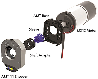
Even in installation and production, the capacitive encoder brings other benefits. Mechanically, its mounting holes are also matched to the other encoder types, making it a fit-and-function compatible unit, Figure 3. Thus, a single encoder can be fitted to different diameter shafts simply by using adapter sleeves, which reduces the number of SKUs (stock-keeping units) in production and repair stock.
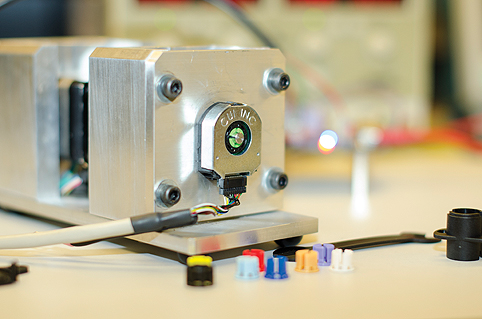
The versatility of an encoder built from a capacitive transducer and custom ASIC electrical interface is illustrated by the AMT11 from CUI, Inc (Figure 4). The small unit, with a 37-mm diameter and a 10.34-mm thick profile, operates from a single +5V supply. It provides both single-ended CMOS incremental-position quadrature (90°) and differential line driver outputs that are electrically compatible with conventional optical- or magnetic-encoder signals. It provides a wide range of programmable resolution choices ranging from 48 to 4096 ppr, plus a once-per-revolution indexing pulse. Axial and radial connection orientations are available depending on the application requirement, along with a operating temperate range of -40°C to 105°C for added durability.
There is a possible concern with the capacitive-based encoder, as there is with any electronic transducer and associated circuitry, namely, susceptibility to electrical noise and interference (EMI). Careful design of the ASIC interface circuitry as well as fine-tuning of the encoder demodulation algorithms has mitigated these issues. The ASIC also offers future opportunities for designs to also include embedded, on-board diagnostics to verify the performance of the encoder mechanism and ASIC itself, as part of a more-intelligent encoder and subsystem.
With the availability of the field-tested encoders based on capacitive-sensing principles, there’s no longer a need for the design engineer to make the difficult choice between the attributes that optical and magnetic encoders force: short and long-time reliability versus output accuracy. The capacitive encoder excels at both, and also brings additional benefits in mechanical mounting, inventory, ppr selection, readout zeroing, and power consumption, all with full compatibility to standard outputs.
Sidebar #1: What about sensorless designs?
Along with using BLDC motors, there’s another, smaller trend as well: the use of sensorless designs which have no need for an encoder indicating shaft position. These motors are controlled by a variety of algorithms including field-oriented control (FOC – also called vector control).
While eliminating the need for an encoder is certainly attractive in theory, the FOC method has several drawbacks: it is not as precise as a sensor-based design, it can lose position and require a re-set, there are control issues at some points in the torque range, and it requires considerable computational effort by the system processor. As a result, it is mostly used in applications where higher precision and consistency in shaft position and speed are not critical, such as consumer appliances (washers, dryers). For most industrial applications, though, the apparent “cost” of the encoder is more than worthwhile, compared to the performance requirements.
Sidebar #2: From caliper to rotary encoder
Capacitive sensing is commonly used for touch switches, where the user’s finger acts as the second plate of a capacitor. Any change in capacitance is sensed by interface circuit, thus emulating the function of a traditional electromechanical pushbutton; they are often used in “open” or public applications such as elevators and crosswalks. Touch switches are known for their resistance to dirt, water, and overall abuse, since they have no moving parts internally and the only exposed part is a small metal tab which is flush with the mounting surface.
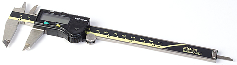
The uses of capacitive sensing go beyond basic on/off switches (either as single units or in an array), with the ubiquitous digital caliper as a mass-market example. Ingvar Andermo, an electrical engineer at the IM Research Institute in Stockholm, was working on a bill-reading application using capacitive technology over 30 years ago. C.E. Johansson approached Andermo about developing a digital caliper using magneto-resistive technology, but Andermo thought that approach was too complicated and decided to use his experience with capacitive sensing.
The first Johansson Caliper, or Jocal, debuted at a 1980 exhibition in Chicago. Johansson later licensed the technology to Mitutoyo in Japan which introduced their first digital caliper using this technology some years later. Since then, millions of such calipers have been sold worldwide, Figure 5.
Andermo eventually worked with CUI Inc., based in Tualatin, Oregon, to develop the AMT Series capacitive encoder using the same technology, this time applied to high-speed rotational measurement. Three elements are present: a high-frequency transmitter, a rotor etched with a sinusoidal-metal pattern, and a receiver board. The rotor sits between the transmitter and receiver boards. As the rotor turns, its sinusoidal-metal pattern modulates the high-frequency signal in a predictable fashion. The receiver board reads these modulations and a proprietary ASIC translates them into increments of rotary motion at encoder resolutions of up to 4,096 steps/turn.
www.cui.com