In recent years, we’ve all become familiar with touch buttons, particularly on consumer electronic devices such as cellphones and tablet computers. Most of these adopt capacitive touch technologies. However, resistive and piezoelectric touch technologies can be better options in many applications. Furthermore, recent developments in software enhanced piezoelectric (SEP) touch will see this flexible, low-cost approach to designing rugged touch controls gain more widespread adoption. This article gives an overview of the main factors that need to be considered in selecting a touch solution and highlights some of the most recent technical developments, including the growing interest in how haptic feedback can be incorporated into touch controls.
Why touch?
The main reasons for adapting any kind of touch technology for a man-machine interface (MMI) are design freedom, to improve the user experience, and to achieve costs savings.
Conventional electromechanical switches are a poor option in every respect. There are thousands of different types but combining them in an attractive way in an MMI is difficult and time consuming. Once designed, it’s then difficult to create control panel variants, or to change the design. They often prove to be the most unreliable component of electronic/electrical systems, particularly where such systems operate in less than benign environments. And electromechanical switches are an expensive and inelegant solution to switching an electrical circuit. Holes need to be drilled, manual assembly is often required, and there are significant design challenges in sealing panels against the ingress of moisture or other contaminants.

An early low-cost alternative: resistive membrane switches
Resistive touch switches comprise two layers of conductive tracks separated by an insulating spacer. Individual switches are defined by holes in the spacer, which allow the conductive layers to come into contact when a finger or stylus pushes them together. Because a mechanical movement of between 0.1mm and 0.5mm is required to make a contact, the graphical panel overlay for the switches has to be quite flexible, limiting the choice of materials. Plastic or metal domes may be used to provide tactile feedback but this can increase the required movement up to 1mm, further adding to the problems of mechanical wear that causes the ‘feel’ of these switches to change over time.
Capacitive touch: no mechanical movement but other limitations
In recent years, cellphones and tablet computers have created a revolution in MMIs, with various forms of capacitive touch underpinning the operation of touchscreens and panels. Switch positions are defined either by a custom pattern or an X-Y matrix of conducting traces on the inner surface of the panel. In the case of a glass-fronted display, transparent indium tin oxide (ITO) is used. Touch is detected when the user’s finger disturbs the electrostatic field generated by a drive signal, creating a capacitive coupling to the receive electrodes or to ground. Sensitivity, speed, accuracy and resolution in registering the intended touch are the trade-offs in design and operation. These factors are affected by moisture or other contaminants on the touch surface and operation can be impaired or prevented if a user is wearing gloves. Metallic overlays can’t be used, so really rugged touch panels are not possible, while inconsistent responsiveness can make it difficult to provide timely visual or audio feedback to the user.
Piezoelectric buttons bring design flexibility and ruggedness to touch panels
Discovered by Pierre and Jacques Curie in the early 1880s, the piezoelectric (meaning pressure electric) effect can be used to overcome the limitations of both resistive and capacitive touch technologies. Equally important, the technology can be implemented at lower cost than capacitive touch.
Natural crystals of quartz, Rochelle salt, tourmaline and manufactured ceramics such as Barium Titanate and Lead Zirconate Titanates (PZT) produce electricity when mechanical pressure is applied by a finger or stylus. There is some mechanical movement but it’s less than 1µm – orders of magnitude less than that of resistive touch panels.
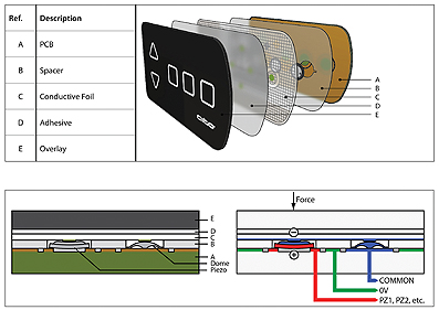
The layered construction of a piezo touch switch is shown in figure 1. Pressure applied to the panel overlay is transmitted through to the piezoelectric disc, or ‘pill’, which sits between a conductive foil and the copper contacts on the PCB.
The top overlay – the part that the user sees – is printed, stamped or embossed with the required information and the RoHS-compliant, piezoelectric pills slot into holes in an insulating spacer. The layer stack, which is usually just added on top of a PCB, can be as little as 0.3mm in depth. In early implementations, piezoelectric buttons suffered from inconsistent operation caused by variations in applied pressure, variations in the composition of piezoelectric materials and temperature-related changes.
Using devices such as the Aito Chip compensates for these variables to enable the creation of piezoelectric touch panels that are stable and reliable, even in demanding environments where other touch technologies may not function at all.

The controller chip, shown in figure 2, performs the following functions:
1. Captures the analogue signal generated by pressure on piezoelectric pill, with sensitivity adjustment achieved by varying the input switching point.
2. Communicates with a host processor via an I2C or SPI interface.
3. Produces a number of outputs to create user feedback, which can be sound (a buzzer), visual (LED indicator) or haptic (a physical sensation).
By detecting both the push and release actions, touch duration can also be measured. This means that each button can perform two distinct functions because ‘touch and hold’ enables a different response.
Note also that haptic feedback is localised to the individual button on the control panel and the vibration experience can be tailored to one of several distinct responses.

This Aito technology has been dubbed ‘Software Enhanced Piezo’ (SEP) and a consortium of companies has established a web site at www.sep-touch.org to promote it.
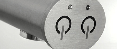
One of the principle advantages of piezoelectric switches is freedom for product designers to use virtually any material, whether an electrical conductor or an insulator, as the panel overlay. Switch assemblies can be flat or curved, and of varying thicknesses. This design flexibility enables engineers and designers to create panels that are not only technically suited to the application but which also add user appeal to the end product. The choice of overlay material can be optimized for the operating environment, perhaps providing protection from moisture, chemicals or even radiation. Figure 3 shows an application example.
Piezoelectric switches are also easily designed to cope with electrostatic discharge (ESD) and to operate reliably in the presence of radio frequency interference, both of which can cause significant problems with capacitive touch panels. Piezo is also an energy efficient solution; capacitive panels have to continually generate an electrostatic field whereas piezo switches generate their own signal when activated, with the chip powered down until an input is received.
SEP development tools, which enable the sensitivity and user-feedback to be tailored for individual touch buttons, include hardware demonstration and evaluation kits, a PC software design suite and software library, and comprehensive documentation. The software library supports the Arduino computer platform, enabling developers to demonstrate hardware prototypes before designing their own embedded hardware.
Summary
Every touch technology has its sweet spot – applications for which it provides the most suitable solution at the lowest cost. Recent advances in piezoelectric touch buttons, particularly SEP with the additional benefit of haptic feedback, are likely to see this technology adopted much more widely due to the freedom it offers designers to differentiate their products through creative aesthetics, the robustness achievable, and the cost-savings that can be realised. n
Links:
This video demonstrates the robustness of a piezoelectric control panel with Aito’s SEP technology.


