


The dream of any engineer designing a 3-phase inverter for an AC Brushless motor is to quickly get a running solution, tuned to his specific motor. But it is a painful experience to extract the intrinsic parameters of a new custom AC Brushless motor. Furthermore, the calibration of the coefficients embedded in the software requires expertise and efforts to reach the expected system behaviour. Each motor and equipment have their own specifications in terms of speed, torque, reaction time and efficiency, nowadays engineers have to struggle to incorporate new motors and electronics in their equipment.
Author: Vincent Mignard, Renesas
Renesas are now offering such a dream tool as an enhancement to their existing RX62T Motor Control Reference Kit (part-name: YROTATE-IT-RX62T) and recently offer it on the latest RX220 Motor Control Reference Kit (part-name: YROTATE-IT-RX220). Both kits are designed to drive any AC Permanent Magnet motors using sensorless Field Oriented Control algorithm. The software running on the RX62T is using float arithmetic and on the RX220, it is using fixed-point arithmetic.
Each kit is based on a single printed circuit using a 32-bit MCU (RX62T or RX220), a power stage using MOSFETs and sensing shunts used to manage sensorless control. The embedded software is royalty free and uses a small flash footprint and minimum CPU resources.
Interfacing to the hardware and developing with a motor is made easy using the highly featured PC Graphical User Interface (GUI).
Finally, the PC GUI enables automatic measurement of the Brushless motor parameters, calibrate the coefficients of the Proportional/ Integral current regulation block and guarantee a safe and reliable start-up process. However, let’s try to understand why the kits and the associated PC GUI may fulfil the dream of any engineer developing new inverter electronics. In the embedded control software and the PC User Interface have two key benefits in mind:
1) Current Proportional-Integral (PI) Coefficients Tuning: Tuning the current PI controls normally requires the use of an oscilloscope and the system performing a current step in order to analyse the step response. Such a feature was designed a few years ago for the Renesas kits, but it a manual and time-consuming process. Renesas’ motor design tool allows PI controls to be tuned easily and quickly, using simply the inverter board connected to the motor together with the PC. Firstly, automatic detection of the correct PI gain values is provided. This delivers the user working values for the proportional and the integral constants for the current. Secondly, the user can refine the tuning by imposing a desired current step and then analyse the step response directly in the User Interface without the need for any expensive oscilloscope, trace debugger and insulation transformer.
2) Motor Parameters Auto-detection: By default, mathematical model parameters of the motor need to be defined in order to start and run the sinusoidal sensorless algorithm. The most important parameters are: the stator resistance; the synchronous inductance and the permanent magnet flux linkages (e.g. the back Electromotive Force constant). The measurement of these parameters is complex and usually requires a fully equipped laboratory with specific instrumentation. Using the new Renesas motor design tool the values of these parameters are automatically identified by the 3-phase inverter itself. The PC User Interface displays the measured values in a few mouse clicks.
Note: In the case of non-isotropic motors, the medium value of the two axes Ld and Lq inductance is provided.
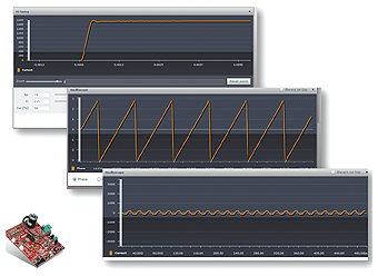
The RX62T and RX220 reference platforms provide a fully isolated USB connection to the PC, so at this point no isolation transformer is needed. The PC Graphical User Interface is able to display all the internal values of the algorithm and it is possible to visualize the step response of the current PI, the phase of the system and the sinusoidal current waveforms as shown on the Figure 1.
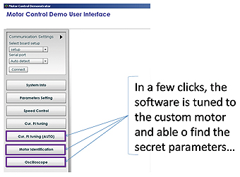
The PC GUI offers three main functions enabling the full calibration with 45 seconds. The first one is the auto-tuning of the current PI, the second is the Motor parameters identification and the third one is the Oscilloscope window as shown on the Figure 2. The five parameters extracted during the process can be stored in EEPROM by a simple mouse-click.
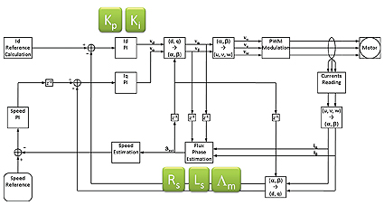
Let’s now dive into the technical mechanisms designed to discover the five main parameters. The blocks structure shown on the Error! Reference source not found. is made with an external speed loop that produces the torque reference. Two internal current loops produce the voltage references, which are applied by the 3-phase inverter.
Using reference systems transformations, the torque and flux controls are decoupled. A large part of the algorithm consists of the reference systems transformations. In particular the transformation between the two-dimensional system reference linked to the stator and the two-dimensional system linked to the rotor. The first is standing, the second is usually rotating, the transformation is called PARK transform and it requires the angular position of the rotor as regards the stator. This position is the position of the permanent magnets flux vector.
To calculate it in a sensorless system, several calculations are performed using the motor model equations. The control loops are performed using standard Proportional Integral (PI) control, which regulates the currents. It is a fundamental part of the motor control algorithm used to control the current delivered to the motor phase. The PI controller is designed to produce a composite output to compensate the error. The two terms of the controllers depends on the Proportional coefficients Kp and Integral coefficients Ki.
The PI is creating a voltage waveform in such a way that the resulting current is following the desired waveform. This is obtained comparing the actual system output with the desired one, and building an opportune system input based on the error itself. The input to feed the system is composed by two terms, one proportional to the error, and the second proportional to the integral of the error.
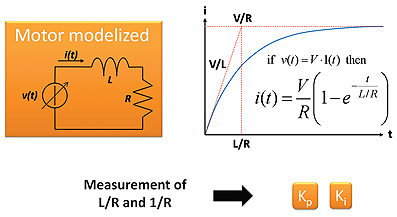
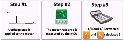
To tune any AC Brushless motors, Kp and Ki need to be extracted. In this case, the controlled system can be seen as an RL circuit. That’s why, the motor model of the Error! Reference source not found. made with v(t) generated by the PI controller, an inductance and a resistance enable the indirect measurements of the mysterious coefficients.
The step response of the circuit is the represented on the left hand side.
The two quotients “L/R” and “1/R” need to be measured in order to find out the Kp and Ki coefficients.
The expected step response of the system is well known. So, it becomes possible to get from the closed loop system the two coefficients: Kp and Ki by measuring: the steady state gain and the time constant of the RL equivalent circuit.
The Error! Reference source not found. is showing the steps used to measures the two quotients and calculate the unknown PI coefficients.
Such approach is fast and implemented on both microcontroller families: RX62T and RX220. It avoids any time consuming manual work and try and error process.
The second benefits of the newest embedded software are the automatic identification of the Brushless motor parameters. In the control algorithm block scheme, the Phase Estimation Block is using the motor model parameters to run properly. The three parameters are: the stator resistance Rs, the synchronous inductance Ls, and the permanent magnets flux amplitude Lm.
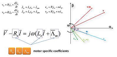
The Figure 6 displays the motor equations used in the embedded software in the flux estimation block. The model used here is referred to the stator. After several simplifications, in the final vector equation, it appears the unknown parameters.
If the embedded software delivers a sinusoidal voltage at a certain frequency, and measure the obtained current, all the quantities in the equation are known, except the three mysterious coefficients.
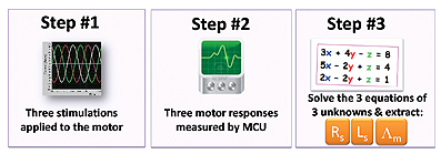
So the procedure implemented is stimulating the motor phases with different voltage waveforms and measuring the corresponding currents. The final step is to solve an algebraic system of three equations of three unknowns as shown on the Figure 7.
Thanks to the powerful PC GUI, the process takes 45 seconds to extract the five parameters: Kp, Ki, Rs, Ls and Lm and finally run an unknown 3-phase AC Brushless motor. Such procedure needs no specific equipment or expensive tools. No specific insulation transformer is required and such auto-tuning is working for low and high voltage motors.
It becomes easy to evaluate different motors in a few minutes for each equipment requirements. There is no fear to have when starting a design of a 3-phase inverter as such tool enable any engineer to drive his own motor in less than a minute and he can spend time on application development.
No deep know-how is anymore needed which shorten the overall learning curve and time to market for the first prototype.
Finally, the procedure is done off-line and requires only a few MIPS from the MCU and little memory footprint.
Up to thirty AC Brushless motors were tuned using the powerful auto-tuning off the shelf solution running either on RX220 or RX62T microcontroller families. Both reference platforms are able to drive 24VDC motors and can control several Kilowatts motors using an external power stage.
Now, it is your opportunity to try the latest Renesas solution by ordering the kits:
• For the RX62T embedding Floating point Unit: YROTATE-IT-RX62T
• For the RX220 using fixed-point arithmetic: YROTATE-IT-RX220
Both kits delivered by Renesas are offered at a cost below €200 per kit and answer the need of a reference design able to drive very quickly a Brushless motors. n
Keywords: auto-calibration, auto-tuning, easy, simple, fast, quick, PC GUI, mouse-clicks, Brushless motors, Permanent Magnet Motors, custom motors, sensorless, parameters identifications, royalty-free FOC software, FOC, vector control, intuitive PC GUI, RX220, RX62T, stator resistance, synchronous inductance, permanent magnet flux.
URLs related to the article:
Renesas RX MCU Family: http://www.rxmcu.com/
RX62T Group: http://www.renesas.eu/products/mpumcu/rx/rx600/rx62t/index.jsp
RX63T Group: http://www.renesas.eu/products/mpumcu/rx/rx600/rx63t/index.jsp
RX220 Group: http://www.renesas.eu/products/mpumcu/rx/rx200/rx220/index.jsp
www.renesas.com