


Brian Chu of Microchip Technology Inc., compares the advantages and disadvantages of different approaches to BLDC motor control.
Author: Brian Chu, Product Line Marketing Manager, Analog and Interface Products Division
Brushless DC (BLDC) motors are gaining increased market share over other motor technologies, particularly in the automotive and medical markets, and this has prompted the development of new approaches to motor-control design. Now, designers have to decide which approach is best for each application.
The traditional approach is to develop the motor-control circuit from discrete components, but more recent developments offer single-chip solutions, based on a System on Chip (SoC) or an Application-Specific Standard Product (ASSP), as well as a two-chip approach. Whilst all of the more recent one- and two-chip solutions offer a reduction in the number of components and in design complexity, each approach has specific advantages and disadvantages. It is these that the designer must understand so that it is possible to make the best possible trade-off between flexibility and space-saving integration.
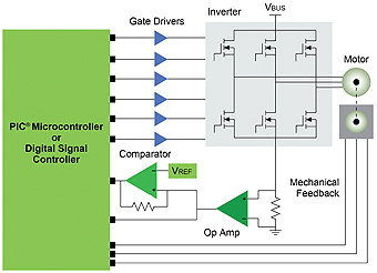
Regardless of which approach is used, a typical motor system is comprised of three main elements: the power supply section, the motor driver, and the control unit. A traditional, discrete-based circuit, as shown in Figure 1, uses a simple RISC processor with on-chip Flash to control the gate drivers which, in turn, drive the external MOSFETs. An alternative method is to drive the motor directly from a processor, with integrated MOSFETs and a voltage regulator to power the processor and the driver.
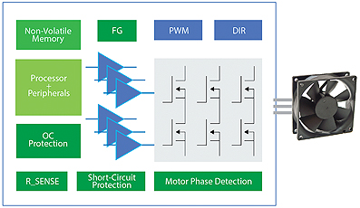
All of these elements are typically integrated into a SoC motor driver. In addition, a SoC offers the benefit of programmability, which enables it to be used across different applications. As a single-chip approach, a SoC is also suitable for applications which have limited board-space. The drawback of using a SoC-based design is that its lower processing performance and limited internal memory mean that it cannot meet the demands of applications which need advanced motor control. A further drawback is that, compared to the broad development toolsets provided by microcontroller manufacturers, there is significantly less support for firmware development in SoC motor drivers. The alternative single-chip approach is to use an Application-Specific Standard Product (ASSP) motor driver, designed specifically for each application. The advantages of using an ASSP are that they occupy minimum space on the board which makes them ideal for space-constrained applications. A 10-pin DFN standalone fan motor-driver is shown Figure 2. ASSPs also eliminate the need for software tuning whilst offering an excellent price-performance ratio in high-volume applications and performance which can match that of a high-end microcontroller. An ASSP motor driver can, for example, be used to drive a BLDC motor using sensorless and sinusoidal algorithms. Despite these advantages, ASSPs lack the programmability which would enable them to be scaled up to higher drive strengths and the flexibility to adapt to future changes in the market.
Whilst the design strategies based on a SoC or an ASSP can help designers to meet the continual trend towards miniaturisation, other applications are using the two-chip approach combining a microcontroller optimised for intelligent analogue in conjunction with an external driver. This approach allows the designer to choose from a broad range of microcontrollers optimised for sensor or sensorless commutation using trapezoidal or sinusoidal drive techniques.
When choosing the companion driver chip for the microcontroller, it is essential that the driver should do more than provide suitable power-ratings for the MOSFET or BLDC motor. It should also integrate a high-efficiency, adjustable voltage regulator capable of minimising power dissipation whilst powering a wide range of microcontrollers. Monitoring and housekeeping blocks are also essential to ensure the safe operation of the motor and to enable bi-directional communication between the host and the driver. Selectable parameters will enable the performance of the driver to be optimised without any additional programming.
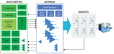
A typical two-chip solution is shown in Figure 3. This approach combines a feature-rich, 3-phase motor driver, such as Microchip’s MCP8024, with a high-performance dsPIC 33EP MC digital signal controller (DSC) to drive six N-channel MOSFETs for the field-oriented control of a Permanent-Magnet Synchronous Motor (PMSM). A lower-cost, baseline 8-bit microcontroller can be used in place of the DSC when using a simple, six-step control architecture.
The change from a DSC to an 8-bit microcontroller can be implemented without altering the drive circuit if a BLDC motor with a similar power rating is used.
The relative advantages of single-chip BLDC motor-control designs, based on a SoC or ASSP, and the two-chip approach using a microcontroller or DSC and a companion driver, are shown in Table 1. This shows that, whilst a SoC or ASSP will meet the needs of a space-constrained application, their fixed feature-sets combined with limited memory and processing power significantly reduce the flexibility and scalability of the design.

The emergence of single-chip and two-chip approaches to BLDC motor control enable designers to reduce component cost and board-space compared to traditional discrete-based circuits. The hardware and firmware reference designs and libraries, supplied by manufacturers such as Microchip, also significantly reduce the development time for bringing an advanced motor-control and drive designs to market.
www.microchip.com