


Electrical current measurement in power electronics applications involves more than just the transducer selection. The path from the transducer to the micro-controller could involve several stages. Each of these stages has an impact on the accuracy of the measurement.
• Offset and gain uncertainties may be added by an intermediate scaling and level shifting stage
• The use of a burden resistor in closed loop applications injects accuracy modifiers
• The final stage of converting the analog current information into a digital format involves the effective number of bits and a final resolution of the current measured
Many power electronic applications require an expanded range for the current measuring device. This expanded range covers the normal operating range (80%-125% nominal current) and coverage for protection (300%). This can have a limiting effect on the dynamic range available control operation.
by Erik Lange, Marketing & Applications Engineer, LEM USA, Inc.
Over Current Detection
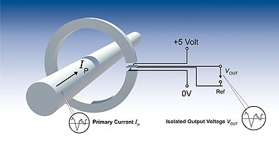
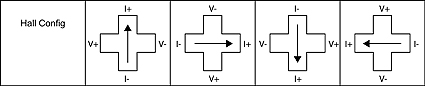
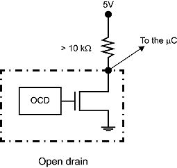
With the advent of ASIC based current detection, options to include other features became available. The ASIC is placed in the gap of the core (see Figure 1). In addition to offset lowering technologies such as Hall cell spinning (see Figure 2.) or programmable sensitivity, the option to include over current detection (OCD) as a separate, programmable output became possible. The OCD changes states, perhaps as an open-collector style output when a trip threshold is exceeded. With an externalized OCD pin, the measuring range of the transducer no longer must include the protection peaks. The entire measuring range can be focused on the dynamic operating range of the application.
The OCD can be programmed for different trip thresholds. This allows for thresholds to be set at 250% or 300%. In the case of the LEM HO series, the programmability extends to 570% nominal rating of the transducer. The over current being detected is beyond the rated measuring range of the transducer.
An 8 amp rated transducer can be programmed for a 45.6A OCD threshold.
The OCD allows for the elimination of a dedicated over current detection crowbar circuit or similar requirement. This frees up board space and reduces the component count. A crowbar circuit may consist of a comparator and several resistors; perhaps 5 discrete components could be eliminated.
Focused Dynamic Range
With the protection function covered by the OCD output, the measuring range is left to focus on the dynamic control range. The transducer is fundamentally going to interact with a 5V or 3.3V device for the analog to digital conversion. If the current magnitude information can be delivered in the 5V or 3.3V range, less intermediate circuitry such as level shifters and scaling will be needed. Most ASIC based transducers are 5V, with 3.3V becoming more available. Historically, the dynamic range has been defined as 0.625V/nominal current for the 5V devices.
This allows for a bidirectional device (AC measurement) to have a zero current point defined as 2.5V out. Current in either direction of flow increases or decreases the output voltage of the transducer from the 2.5V start point (zero primary current).
For example, in the case of a 10A application (10A equals 100% load), the transducer would have a nominal rating of 10A with a 30A peak rating to provide for protection. The sensitivity of 0.625V/10A (LEM HXS 10-NP/SP4 for example) allows for 300% reading (30A or 4.375V output) for protection. The Volts/Amps are 0.625V/10A or 62.5mV/Amp.
Magnetic Multiplication
The method of multiple wraps of conductor in serial through a transducer is a known technique and is often referred to as ‘Magnetic Multiplication’. This is useful when a current transducers rating is above that of the applications primary current. It is important to utilize as much of the transducers dynamic range as possible to minimize offset and linearity errors. The conductors magnetic fields sum to a multiple defined by the number of wraps in serial. This will be shown in the following AC & DC application examples.
AC Application
With the OCD monitoring for protection, the entire dynamic range can be utilized for control. The above 10A example application can be applied to a 15A transducer (LEM HO 15-NP).
The current is wrapped through three times in serial on the three separate bus bars. With 125% of the nominal rating of the application as the upper range, the current will appear to be as high as 37.5A for a maximum. At 100% duty (10A), the transducer sees 30A. An original sensitivity of 53.33 mV/A (HO 15-NP) will correspond to a resulting sensitivity of 160mV/A. This compares to the 62.5mV/A of a standard 10A nominal transducer by a factor of 2.56.
The lower currents are lifted higher out of the noise floor and the available dynamic range is more utilized. That is an example of an AC application where both sides of the 2.5V zero current point need to be utilized by the application.
Unidirectional DC Application
In a DC example that is unidirectional in nature, the Vref can be utilized to dramatically expand the dynamic measuring range. Starting with a LEM HO 8-NP and wrapping the primary current three times in serial, a maximum (125%) current of the application is achieved of 37.5A. With the Vref pulled or programmed to 0.5V representing 0A, the 100mV/A sensitivity of the transducer can be fully realized. The peak voltage output at 37.5A is 4.250V, a breadth of 3.75V for a change of 12.5A or 300mV/A. A DC application that in the past would operate at 62.5mV/A can now operate at 300mV/A. In a 5V/12bit application, a bit represents 1.22mV. The output voltage would range between 0.50V and 4.250V representing a current of 0A to 12.5A and a range of 3072 bits. In a traditional 10A application without Vref shifting and no OCD, the 0 to 12.5A operating range would be represented by a voltage of 2.5V to 3.28V.
This range of 0.781V represents 640 bits. The bit resolution is 4.1mA for the Vref shifted/OCD method or 19.5mA without the ASIC based features.
The Vref shifted/OCD combination will give much finer control of the current.
Not all ASIC based transducers allow for the maximum range of currents. The LEM HO 8-NP allows for the increased dynamic range. However, the LEM HO 25-NP does not allow for such a broad multiple of measuring range when the Vref is pulled to 0.50V.
Typically the lower current range transducers in a series will have a broader range available than the higher current members of a transducer family.
Heat Dissipation
In smaller transducers, when the dynamic range is fully exploited, the conductors will generate heat in the single digit Watt range. Integral bus bars will have sub milli-Ohm resistance. But with currents in the 150A range, even the 200μOhms of the LEM HLSR 50-P will begin to generate 4.5 watts.
Modern ASIC based transducers will typically allow operation in the 105°C to 125°C range. In the case of ASIC based transducers with bus bars there may be maximum bus bar temperature limitations (120°C being a typical value). Thus higher heat generation will not be an issue if heat dissipation is taken into account. PCB traces and copper surrounding the transducer pins should be maximized, not minimized, to assist in heat dissipation. Air movement will play an important role. A challenge is sizing the traces to the transducer to the minimum dictated by the design current. Minimally sized traces will not sufficiently wick away heat and even a high ambient (85°C) could possibly result in de-soldering of the transducer.
A thorough check of the final designs operating temperatures should include core, solder joint and bus bar temperatures.
Conclusion
The implementation of an expanded dynamic range through use of ASIC based transducers with OCD capability has several benefits:
• Reduced component count and increased reliability as the number of discrete components decreases
• Better resolution from the analog to digital converter
• Increased sensitivity being the best gain overall as the amount of volts per amps increases
• Improved signal to noise ratio
An ASIC based current transducer with OCD capability takes current measurement a leap forward in resolution, sensitivity, reliability and noise immunity.
www.lem.com