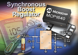
Boosting a single battery can replace multiple batteries to cut costs and size, explains Jason Tollefson, Mikhail Voroniouk, and Adam Jakubiak, Microchip Technology Inc. and Energizer Battery Company
Whilst rechargeable batteries are suitable for applications which have high levels of used combined with higher drain rate, a primary battery is still the easiest and lowest-cost design option for most portable devices and the one which can support a significant reduction in physical size.
Regardless of whether the design is for a medical blood-glucose meter; a PC peripheral, or a camera, the goals will be to deliver intelligent control combined with the longest possible battery life, and reducing the size and weight of the end-product to make it more portable.
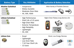
Of course, deciding to implement a single-battery design is just the start: there is then the decision to be made on which battery technology to use. Figure 1 shows a range of popular primary battery technologies, and their typical applications.
For timers and watches, which have a comparatively low energy draw combined with an operational life of up to 10 years, small, lightweight lithium coin batteries such as Li/MnO2, are available in 13 different sizes.
For portable products which have a low to medium drain rate, alkaline cylindrical batteries are available in three compact form factors: AA, AAA, and AAAA packages.
Cylindrical lithium (LiFeS2) batteries offer just two form factors, AA and AAA, and are most suitable for applications with a medium to high drain rate, or which need to operate in cold temperatures. Compared to cylindrical alkaline batteries, the lithium alternatives are 33% lighter, provide higher reliability and have a shelf-life of up to 15 years which is two or three times more than alkaline batteries.
Single-battery designs
Higher silicon integration and smaller passive components mean that the size of portable products is shrinking year on year. For most designs, the barrier to further reductions in size is the physical size of the battery cavity which may need to allow space for two or more batteries. The alternative is use a microcontroller which can run on a single 1.5V battery.
A battery boost converter, such as Microchip’s MCP1640, provides a power supply by stepping up an input voltage up to a higher, regulated voltage, such as 2.0 to 5.0V. This means that the device can start up with an input voltage which is significantly lower than the operating voltage.
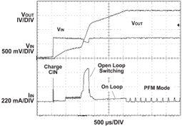
Many microcontrollers, for example, cannot operate with a voltage which is lower than 2V, whereas the boost converter can provide the voltage from a startup voltage as low as 0.65V. Figure 2 shows a typical startup waveform, where the low-voltage startup begins to charge the output voltage up to the input voltage. Once the output voltage is charged, the N-Channel begins to switch, pumping the output voltage up, after which the internal bias switches from the input to the output. This enables an application using a boosted single alkaline battery to start up at any point in its discharge curve, provided that it has enough remaining capacity to operate the device.
While a battery boost converter may be able to deliver a consistent output voltage from very low input voltages (for example 0.35V), battery suppliers, such as Energizer, do not recommend discharging alkaline or lithium batteries below 0.8V, as it can damage the battery.
The advantages of using a single-battery approach depend on which type of battery is being replaced. For example, by replacing two alkaline batteries with a single alkaline battery saves both the space and the weight of the second battery although there is a tradeoff in the small amount of space required by the converter and its supporting components.
Using a battery boost converter also maximises the system power efficiency by providing regulated power over the battery’s entire operating range. This regulated voltage can make the microcontroller operate more efficiently, by enabling it to run at a lower and flatter voltage. For example, reducing the microcontroller operating voltage from 3.3V to 2.2V provides 1.8 times lower power consumption on the microcontroller side (voltage difference squared). Additionally, the boost converter provides short-circuit protection through current limiting.
The OEM cost for implementing the boost converter with a single battery is a little higher than the cost of two alkaline batteries, but the consumer operating cost can be similar between the two approaches if the boost converter is operating at high efficiency. Adopting a single alkaline battery approach enables developers to shrink their product size without switching between battery chemistries from a legacy multi-battery alkaline design. Working with a single battery also simplifies the mechanical considerations of the battery housing and reduces the risk that batteries will be installed incorrectly by the user.
Designers comparing the advantages and disadvantages of implementing a single alkaline battery versus a rechargeable lithium ion polymer battery will find similar but different reasons for selecting the single-battery approach. Because the boost converter provides a regulated power output, it allows the tuning of the voltage to maximise system efficiency. Similar to the alkaline example, the boost converter provides short-circuit protection through current limiting. The 352mm2 footprint for a single AAAA alkaline battery is smaller than a single lithium ion polymer battery at 650mm2 (31.0 × 21.0 × 3.5mm), even though they have the same volume (2.3 cc), assuming a two-sided board design.
Using an alkaline implementation versus the lithium ion polymer simplifies logistics because it avoids the need for charging circuitry and conforming to lithium shipping regulations. For those applications where using a replaceable battery is more convenient, implementing a boost converter with a single AAAA alkaline battery can provide a 50-70% cost reduction for the battery portion of the system compared to a single lithium ion polymer battery plus a charge controller and charger.
Comparing a single alkaline battery implementation versus a lithium coin battery demonstrates yet another set of conditions where the single battery approach is favorable. For this example, the comparison is between an AAAA alkaline battery with a 600mAh rated capacity and a CR2032 lithium coin battery with a 225mAh rated capacity. Similar to the lithium ion polymer example, using a single boosted alkaline battery avoids the need to conform to lithium shipping regulations. Cylindrical batteries, such as the AAAA, are more familiar to consumers than the coin batteries, and this makes it easier to ensure the battery is installed correctly.
The footprint of using either power source is similar, with the single alkaline AAAA battery taking approximately 352mm2 compared to 314mm2 for the CR2032 lithium coin battery, assuming a two-sided board.
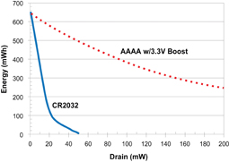
The single alkaline battery continues to benefit from the tunable voltage to maximise efficiency and provide short-circuit protection through current limiting. However, unlike the CR2032, the alkaline battery is able to deliver a higher continuous current. Specifically, the boosted alkaline battery can source 150mA continuously, while the CR2032 can only do that for very short pulses. Extended continuous current beyond 10mA from the CR2032 battery dramatically decreases its usable capacity and, even at 20mA, it can only deliver 1/5th the energy that boosted AAAA batteries can provide, as shown in Figure 3.
System-level trade-offs
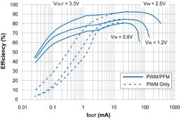
While using a battery boost converter provides many advantages, such as enabling a microcontroller-based design to operate with a single battery, it is important to consider the system-level tradeoffs between a boosted single-battery implementation and a multiple-battery design. The efficiency of the battery boost converter is highly dependent on the current draw, as well as the input and output voltages. The dominant loss for a boost converter is resistance, so the efficiency of lower input/output voltages is lower than the efficiency of higher input/output-voltage applications, as shown in Figure 4. Other factors that can impact the boost converter’s efficiency are the resistive losses in the inductor and capacitors. Inductors with lower DC-series resistances, and capacitors with low ESR (Equivalent Series Resistance), allow higher efficiency with the potential trade-offs being size and cost.
To support a lower system current draw, the boost converter may include a low quiescent operation mode that typically draws 20?A, and a shutdown mode that draws less than 1?A. When coupled with a microcontroller, a booster can provide a voltage to power the application in a sleep mode, using a coast-down method. The microcontroller turns on the boost circuit when the system voltage falls below a pre-determined level, then shuts it off to eliminate the operating current of the booster while continuing to power from the booster’s output capacitor. Using this method, the total power consumption of the MCU and the boost regulator can drop by as much as 87%.
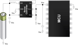
Implementing a battery boost converter does enable a design to reduce the overall system area by the size of the second battery, with the trade-off of including the boost converter, two resistors, two capacitors and an inductor, as shown in Figure 5. The weight of the boost converter and its accompanying components is negligible for most designs. The area of a typical boost-converter circuit is approximately 60mm2, which is considerably smaller than the 450mm2 area of a second AAA battery or the 352mm2 area of a second AAAA battery, and still yields a 290 to 390mm2 area reduction in the overall system, assuming a 2-sided board design. The OEM cost to implement the boost converter and its accompanying components is about $0.20, which may or may not be offset by the alternative battery technology which is being replaced.
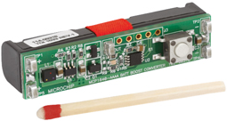
Many semiconductor companies offer application notes and/or reference designs for their boost converters, such as Microchip’s MCP1640 single AAAA battery boost converter reference design, shown in Figure 6. Modifying this pre-engineered circuit for a specific application can save a considerable amount of design time.
End-product benefits
A boosted single battery implementation not only enables differentiation through a smaller form factor for many applications, but it can provide a cost advantage over using coin or rechargeable batteries. Being able to minimise the width and weight of an electric toothbrush’s handle enables the handle to feel more natural in a user’s hand.
Using a single battery also simplifies the mechanical design effort to ensure that the user has installed the battery correctly.
Another benefit of using a boosted battery is that the power supplied to the device is regulated, so that it receives a flat voltage profile throughout the life of the battery. This enables the toothbrush to provide a consistent vibration throughout the life of the battery, without a noticeable drop-off in vibration strength and performance, as the battery discharges. Additionally, the microcontroller can modulate the vibration signal, such as generating pulsating vibration to signal to the user that the battery is approaching an end-of-life condition.
Flashlights, especially LED flashlights, can also benefit from a regulated supply voltage by using the boost converter to power a microcontroller, which in turn controls a more complex supply for the LEDs. The regulated supply can avoid a dimming of the flashlight as the battery discharges to provide consistent lighting through to the battery’s end of life.
Using a boosted, single alkaline battery can be appropriate in value-priced devices, such as a portable, wireless mouse. A value-priced mouse focuses on longer battery life by operating with low-frequency positioning updates appropriate for Web browsing and text editing, as opposed to higher-frequency updates for gaming. Wireless mice are able to deliver a compact form factor with the single replaceable battery, and save on design and materials cost versus implementations that rely on a rechargeable battery. In addition to the cost difference between the battery technologies, using a replaceable battery means the mechanical design avoids including an expensive connector for a recharging source.
Most consumers are familiar with AA, AAA, and AAAA cylindrical form factors, and they know where to acquire them. Designs using these form factors can provide a simpler access hatch to replace the battery, so that the user is confident the battery is installed correctly. While other form factors, such as a coin battery, are not unusual, most consumers are not as familiar with the notations for the different coin form factors – nor are they as familiar with ensuring that the battery is installed correctly. The clear orientation for installing a cylindrical battery and ease of acquiring replacement batteries provides an ease-of-use differentiation for a design.
Boosted equipment can also be differentiated by incorporating RF connectivity in the volume that was freed up by using a single battery. Applications that can benefit from this are portable medical equipment, such as blood-pressure modules and blood-glucose meters, as well as beacons used in industrial environments for tracking transportation containers.
Summary
Replacing multiple-battery designs with a single battery and a battery-boost converter, such as Microchip’s MCP1640, has real benefits for a wide range of portable applications. Using a single boosted battery can enable designs to gain a competitive edge by becoming smaller and lighter, with a lower cost of materials and more straight-forward mechanical design than using multiple batteries. End-users benefit too because of the wide-spread availability and familiarity with cylindrical batteries. All of these are valid reasons for moving to a single-battery design for portable devices.
www.microchip.com


