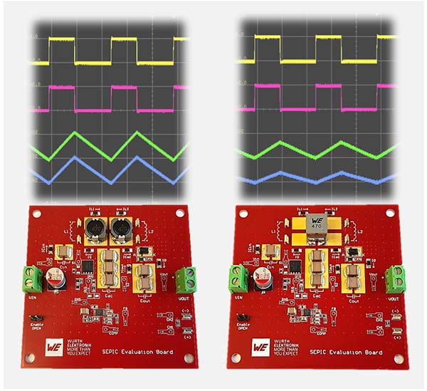
SEPIC boards for Würth Elektronik’s new application note: with two uncoupled inductors (left), with a coupled inductor (right). — Image source: Würth Elektronik
In Application Note ANP135 “The SEPIC with coupled and uncoupled inductors”, Würth Elektronik addresses the operation of a Single-Ended Primary-Inductor-Converter (SEPIC) in both continuous and discontinuous conduction modes (CCM and DCM). The 28-page document also includes design considerations and guidelines with focus on the power magnetics.
The SEPIC is a non-isolated switching power supply topology generating an output voltage that can be higher, equal or lower than the input voltage. Typical applications include battery-powered devices and chargers, automotive power systems, photovoltaic converters, LED lighting, and power factor correction stages. This new Application Note from Würth Elektronik provides a detailed analysis of the SEPIC converter with particular emphasis on the implementation with a coupled inductor, such as the WE-MCRI. It also includes an analysis of “ripple current steering” technique and the key role that the leakage inductance plays in the converter, all supported by SPICE simulations and measurements on a real DC-DC SEPIC converter prototype.
Coupled or uncoupled
Unlike topologies with a single inductor, such as buck, boost or buck-boost converters, the SEPIC power stage requires two inductors. These can be implemented as uncoupled, separate inductors, or alternatively configured as a coupled power inductor with two windings on a common core. This configuration not only reduces the number of components but also requires less inductance to generate the same ripple current amplitude compared to a solution with uncoupled inductors. Moreover, the magnetic coupling of the windings enables the implementation of “ripple current steering”. This is a technique in which the ripple current of the input winding can be “steered” to the output winding, helping to reduce conducted EMI noise.
“When designing a SEPIC with coupled inductors, it is important to understand the influence of the coupling factor on the converter performance. In contrast to typical scenarios, a higher leakage inductance can be of advantage in this case,” explains Eleazar Falco, Senior Application Engineer at Würth Elektronik eiSos and author.