


The art of power supply design, like most worthy endeavors, is a never-ending challenge of balancing several objectives to reach the most desirable outcome. For switched mode power supply (SMPS) designs, competing objectives typically include total system cost, form-factor limitations, overall efficiency specifications, thermal concerns and time-to-market pressures. Occasionally, a new idea breaks upon the scene, dramatically changing the power landscape.
By Bob Neidorff and Thomas Lewis, Texas Instruments
Global demands for lower overall system costs and thinner profiles have lead to interleaved power factor correction (PFC), the industry’s latest breakthrough. The concept of interleaved PFC was discussed as early as 1992 by Miwa, Otten, and Schlecht[1]. Single-chip interleaved PFC control became a reality in 2007, and is now radically changing the face of several end equipments over night – most noteworthy digital TV. This article addresses the need for PFC and the latest breakthrough in design thought. It should prove especially helpful to engineers facing difficult design specifications on a limited budget, and those simply interested in learning more about this new trend.
Typical PFC
A typical PFC circuit is a boost switching regulator with control circuitry. It maintains input current proportional to instantaneous line voltage, while simultaneously regulating output voltage (Figure 1).
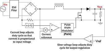
The feedback loop that regulates current has a bandwidth of approximately 10kHz. It smoothly regulates average input current proportional to input voltage so that power factor is very high, and harmonics are minimized. The voltage regulating loop has a bandwidth much lower than 60Hz so that it doesn’t interfere with the current loop. Often, non-linear feedback elements are added to the voltage loop to improve response to large input and output steps.
For heavy load currents, boost switching regulators maintain continuous inductor current, typically with 60 percent current ripple. Low ripple current can be advantageous because it attenuates easier with the input EMI filter. For lighter load currents, current ripple can increase to 200 percent. The input current can even go discontinuous, as long as the current loop controls average input current.
Another practical way to produce input current proportional to input voltage is to use a “transition mode” converter with regulated on-time, which remains constant throughout the line cycle. Transition mode, or “critical conduction mode”, means that the converter starts a new switching cycle every time that input current decays to zero. In other words, this is the boundary between continuous and discontinuous conduction mode. By definition, transition mode has 200 percent ripple current. With a transition mode boost switching regulator operating with fixed on-time, average input current is inherently proportional to input voltage. For any switching cycle, peak current is Ipeak=Vin*Ton/L and valley current is zero. Therefore, average input current is half of peak current: Iaverage=Vin*Ton/(2*L). As long as the inductor and on-time stay constant, average input current is directly proportional to input voltage.
Fixed on-time transition mode has many advantages such as no current feedback is required. Thus, much less power is lost in sensing current. Another advantage is that the converter is immune to errors in the current sense circuit. A third advantage is that the converter always starts a new switching cycle with zero output-current, minimizing diode switching losses. Transition mode converters can operate efficiently with inexpensive silicon diodes, as long as they have moderately fast-switching speed. Comparatively, continuous current circuits often require expensive silicon-carbide diodes for high efficiency.
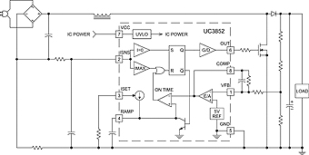
Figure 2 shows the schematic of a fixed on-time power factor corrector built around an inexpensive 8-pin transition mode control IC. This circuit uses a current-sense resistor to detect zero current and over-current faults, but otherwise does not rely on precision current sensing. With this IC, current is limited to less than 425mV across the current sense resistor. By comparison, typical power factor control circuits using current feedback have maximum current limit signals between 1V and 2V, greatly increasing power lost in the current sense resistor.
Why Interleave?
All switching supplies conduct some portion of switching energy onto the power line through current ripple. Current ripple can be larger, as with a transition mode PFC with 200 percent ripple, or smaller as with a continuous current mode PFC with 60 percent ripple. Although this represents a 10dB improvement, it comes at the expense of a larger boost inductor. Regardless of approach, some form of EMI filter is required.
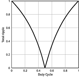
If we built two identical PFC circuits and operate each 180° out-of-phase, the combined two-stage ripple current would be significantly less than the single-stage ripple producing the same total power. Hence, a much smaller input EMI filter could be used. Operating two stages at exactly 50 percent duty cycle reduces ripple to zero! At different duty cycles, ripple reduction is lower, but still significant. Operating two identical stages 180º out-of-phase is called interleaving, which is practical today thanks to modern highly integrated circuits. Figure 3 shows reduced ripple current achieved by interleaving two power stages for different duty cycles.
An advantage of interleaving is reduced output ripple current. This allows for a smaller output capacitor, or less current stress on the original capacitor selection – resulting in longer life and higher reliability. Another advantage is that two smaller versus one large component can be used. This includes the boost inductor, power MOSFET, and power diode. These smaller components enable distributed board layout, which dissipates heat from various power devices and enables lower profile power systems.
Interleaving also enables higher power than would be practical with a single-phase architecture. Two existing 250-watt, single-phase PFC stages can be easily interleaved, quickly developing a 500-watt power PFC from the same parts.
Typical Interleaved CCM PFC
Figure 4 shows a complete interleaved continuous current mode PFC built around the UCC28070, an interleaved PFC controller IC. This fixed-frequency controller includes all of the control circuitry required for two interleaved PFC stages, as well as frequency dithering.
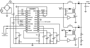
This PFC design uses current-sense transformers T1 and T2 to monitor power MOSFET drain current. This produces a signal that represents current when the power MOSFET is on. Inductor current during the remaining switching cycle is reconstructed by the IC, based on input and output voltage. This current synthesis technology uses only two current transformers versus four to reconstruct the inductor current, reducing overall system cost.
The IC regulates current in each inductor with two independent, fast, average-current feedback loops. The overall slow voltage feedback loop is shared by two current loops. In this way, the two current loops have the same current reference and ensure current balancing between two channels.
This PFC operates at a switching frequency set by RRT. If a very dense power supply is required, this design can operate at switching speeds of up to 300 kHz or higher, allowing very small inductors to be used. For highest efficiency, however, switching at < 75kHz is recommended. Frequency dithering, which further reduces EMI noise, is also implemented and programmed by capacitor CCDR and resistor RRDM. Maximum duty-cycle is set by RDMAX.
Soft-start is programmed by CSS. This design operates in continuous or discontinuous mode, depending on the load current. Therefore, high-speed silicon carbide diodes are recommended for D1 and D2.
Select the output capacitor, COUT, to permit downstream converter operation during the longest expected line dropout. Although not shown, input EMI filtering is usually required.
Typical Interleaved TM PFC
Figure 5 shows a complete interleaved transition mode PFC built around the UCC28060, the industry’s first interleaved PFC controller IC. This design takes advantage of the frequency modulating inherent in transition-mode control.
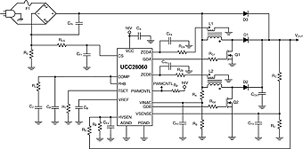
This spreads the EMI spectrum and reduces required EMI filtering. The UCC28060 also implements phase management, a powerful technique for improving total efficiency by switching between two-phase operation at heavy load, and one-phase operation at light load.
Advantages of the UCC28060 are that low-cost diodes and smaller inductors can be used. Inductors L1 and L2 each have a second winding for sensing zero inductor current and starting a new switching cycle. Resistors RZA and RZB combined with capacitors CF4 and CF5 remove signal noise. They also provide a small time delay, allowing the MOSFET drain to resonate down to its lowest level. Although not perfect, this approximation to zero-voltage switching can improve efficiency by minimizing the energy lost discharging the power MOSFET drain capacitance as the power MOSFET turns on.
This converter uses fixed on-time control to achieve high power factor, so individual power MOSFET currents are not sensed. One overall current sense resistor, RS, is used to prevent switching during turn-on inrush and to stop switching in the unlikely event of over-current.
Switching converters with a constant load have negative input impedance at low frequencies. In other words, as input voltage increases, voltage feedback reduces input current to maintain constant output voltage. This can cause the EMI filter to become unstable. To minimize this risk and help reduce input EMI, use a small high-voltage capacitor CIN on the bridge rectifier output. For a 300-watt converter, a 1 F capacitor may be sufficient. This capacitor value should be as low as possible to save cost and maintain high power factor at high line.
This converter uses two independent paths to sense output voltage. One senses output voltage using pin VSENSE and divider RC and RD. This sense circuit is used to regulate output voltage and to shut down the converter in the event of output over-voltage. The second path uses pin HVSEN and divider RE and RF. The second path implements a redundant over-voltage sensing for safety. It also senses the output voltage to switch on the load. Logic output PWMCNTL asserts low when the output voltage is high enough for operation. PWMCNTL de-asserts (goes high impedance) when the output voltage falls below the dropout threshold, or when one of the power stages has a fault.
Dealing with Light Load
Converters are engineered for many performance attributes at full load, including peak efficiency, safe operating temperature, reliable component operation, and ability to operate through a power line dropout. However, performance during light-load operation is also important. Standards like Blue Angel and Energy Plus set efficiency standards at full load and light load.
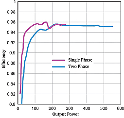
Figure 6 compares the efficiency of a typical interleaved PFC operating in both single-phase and two-phase modes. Although interleaving gives excellent efficiency and reliability at full load, light-load efficiency is higher with only one-phase switching. This is because energy consumed slewing drain capacitance becomes more dominant at light load.
A practical interleaved PFC should switch to single-phase operation at light load. The optimum crossover point is a function of line voltage and other design variables. To facilitate Blue Angel and similar standards, switching to single-phase before 20 percent load realizes maximum benefit.
At no-load, standards demand extremely low quiescent power consumption. While today’s Energy Star® standard allows no more than 0.5 Watts, future standards will require under 0.3 Watts – and even lower standards are expected. To achieve this ultra low power consumption, the most practical solution is to completely disable the boost PFC, and run the downstream PWM from the unboosted, rectified power line.
The UCC28060 interleaved transition mode PFC (Figure 5) contains circuits for phase management that switch between two-phase, one-phase and shutdown, dependent on load.
Minimizing Acoustic Noise
Capacitors, inductors, heat sinks and shielding can vibrate audibly due to signals from the switching converter. Switching converters operate above 20kHz, but certain line and load conditions can stimulate audible vibrations.
One example is transitioning from full to light load. Although the output capacitor decreases the effect of the load step on the converter, the converter must still change on-time or duty-cycle by a large amount to regulate output voltage, while the voltage regulation loop must be slow to provide good power factor.
In this example, some output overshoot is inevitable. If overshoot is too high, the output capacitor or following power converter could be damaged. Thus, PFC ICs like the UCC28060 contain error amplifiers with fast, non-linear response to very large overshoot. For some load steps, this quickly brings the output back into regulation. But for the worst steps, even these fast, non-linear loops can’t respond quickly enough and the output over-voltage protection will trip, switching off the converter. The converter will restart when the output drops below the lower over-voltage threshold. This can take a few low-frequency cycles of high-output over-voltage followed by zero load decay before the loop is back in regulation.
These low-frequency cycles may be audible or otherwise undesirable. To prevent this issue, some PFC ICs like the UCC28061 shutdown and restart slowly in response to a severe overshoot. The UCC28061 is very similar to the UCC28060, but is optimized for systems with very wide load range.
Conclusion
The era of interleaved PFC has arrived and, with it, ushers in new advancements for power supply designers across the globe. Higher efficiencies, in smaller form factors, at the same or lower overall system cost are now obtainable. That’s a trend worth talking about!
[1] “High efficiency power factor correction using interleaving techniques” Miwa, B.A.; Otten, D.M.; Schlecht, M.E.; APEC ’92. Conference Proceedings 1992; pp 557-568; Digital Object Identifier 10.1109/APEC.1992.228361
www.ti.com/pfc
Contact Romania:
Irina Marin
ECAS ELECTRO
irina.marin@ecas.ro
Tel: +40 (0)21 204 8100
www.ecas.ro