


Developing a user interface is now one of the biggest challenges in embedded system design; do you choose an intuitive but conventional electro-mechanical interface, or a graphical interface which offers more flexibility but demands increased system resources? The decision is often driven less by need and more by desire; as a result designers must balance desire against functionality while maintaining control over production costs. This article provides some insight into the various user-interface options currently available, presenting examples of how these options can be used and providing some idea of the impact they have on system cost and processing.
Stephen Porter, Principle Applications Engineer, Home Appliance Solutions Group, Microchip Technology Inc.
Keith Curtis, Technical Staff Engineer, Security, Microcontroller and Technology Development Division, Microchip Technology Inc.
To emit, or not to emit
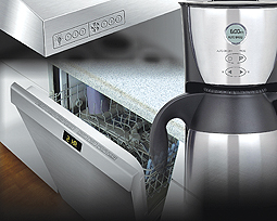
Display systems typically fall into a few broad categories, usually based on their basic technology, such as LED and LCD displays. These systems have both advantages and disadvantages, but overall they are generally capable of producing similar types of displays. The exact format of the displays varies, but the main categories are single indicators, segmented displays and graphics modules.
LED displays involve time-proven circuits that are microcontroller-friendly. In fact, most microcontrollers (MCUs) utilize general purpose input/output drivers with sufficient current capabilities to drive LEDs directly, with only a simple current-limiting resistor, because LED displays require only a few mA of drive. LEDs are also available in a wide variety of both individual indicators and segmented displays. However, due to their accumulated heat dissipation, they are generally precluded from larger graphic modules.
LCD displays utilize a liquid crystal fluid to either block or pass light through the display. Segmented and indicator LCD displays require low amounts of energy to switch the liquid crystal, making them MCU friendly, but they do rely on an external light source or a backlight to provide the necessary illumination, they also have a relatively limited temperature range.
Many small MCUs are capable of driving indicator and segmented displays with few external components, while some MCU manufacturers such as Microchip Technology provide complete graphic function libraries to assist in the development of graphic applications.
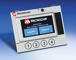
Figure 1 shows an example of a user interface that demonstrates several types of displays and user inputs.
This example makes use of the 16-bit PIC24F MCU to handle all of the inputs and outputs of this reference design.
Touch screens are an attractive alternative to electro-mechanical interfaces; the display’s entire surface is a user input, allowing the designer to redefine the user input on-the-fly by creating multiple, simpler interfaces.
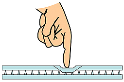
On the other hand, electro-mechanical inputs involve switches, rotary encoders and potentiometers, and these items bring with them challenges such as mechanical wear and tear, mounting difficulties, and difficulties associated with sealing the interface against dust and moisture. However, mechanical technology is also used in resistive touch screens. Here, the user pushes two plastic layers together, creating an electrical connection that can be read using current drivers and Analog-to-Digital Converter (ADC) channels. Figure 2 shows a cross section of a resistive touch screen. This is a simple system, but it is subject to wear and tear, and it can require system calibration, filtering or linearization to compensate for physical variances. Mechanical contact systems rate high for ease of interface to an MCU, even though a simple algorithm to debounce the contacts is still a necessity.
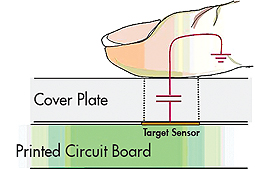
Capacitive touch is another possible appliance user-interface option. This technology takes advantage of the basic construction of a capacitor—namely, two conductors separated by an insulator. When this field is applied to the iron in our blood, the system capacitively couples every surface of our body; from the tips of our fingers to the soles of our feet. Capacitive touch works by measuring the capacitance change caused by a finger touching the cover over a conductive plate. This increase in capacitance is measured and compared against the unpressed capacitance of the plate. Figure 3 shows the model for capacitive touch. If a sufficient shift in capacitance occurs, then the sensor is considered touched and the corresponding functions are activated. The primary requirements for the system are a sensor plate, an insulating covering such as glass or plastic and some means of measuring the capacitance with sufficient resolution. Several MCUs have built-in capacitive sense modules, such as some 8- and 16-bit PIC® MCUs.
For the ‘button and knobs’ format, it is simply a matter of creating the appropriate sensor pads, capacitance-measurement circuitry and the software to drive it. Some MCU manufacturers supply reference designs and supporting development tools to make this job easy. The only challenge is developing an appropriate averaging algorithm to determine the untouched capacitance of the sensor. Capacitive touch is also quite prevalent with touch screens, with two main forms currently available—surface-capacitive technology and projected capacitance.
Surface capacitive technology uses the finite resistance of an indium tin oxide layer on the back of the sensor. When the user touches the sensor, they form a capacitance to ground, which AC shorts the sensor at the point of the touch. The interface then determines the touch by measuring the current drawn by the sensor when each edge of the sensor is driven by an AC waveform. The relative currents are then used to calculate the distance from each edge to the user’s touch. Because the sense signal is in the MHz range, the design is often left to companies that specialize in the technology.
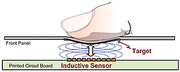
Projected capacitive touch works by creating two layers of touch sensors, one which is a series of horizontal stripes, and the second that is a series of vertical stripes. The interface electronics interrogate the system in order to determine which horizontal and vertical stripes are closest to the user’s press and interpolate a final position. Projected capacitive systems are generally simpler than their surface capacitive brethren, but they do have to scan many more inputs to detect a touch, which tends to increase system overhead and slows its response. Many of today’s kitchen appliances involve finishes that consist of metal, plastic and glass. Sometimes appliance designers use a combination of these, to provide the sleek look that today’s appliance consumers want. For example, stainless steel is a finish often seen on appliances. However, with stainless steel finishes, appliance manufacturers must still use stainless-steel looking plastic or even glass plates to implement the capacitive-touch control buttons. Technology and manufacturing costs can impact the overall feel of the products with this approach. How can appliance manufactures get around this? The answer is the final user-input technology that this article will discuss—inductive touch sensing. Inductive touch enables appliance designers to utilize metal such as stainless steel or aluminum as the main surface of the product, itself, for sensing deflections (see Figure 4 on the top). This is accomplished by mounting a specifically-designed circuit board behind the metal, where the buttons are to be placed. A thin spacer layer is used to create a small gap to enable the metal to be slightly deflected. The amount of deflection required is very small, as shown in Figure 5. The circuit board can also be the main control board for other functions, as processor requirements and usage are low for this technology.
In addition to providing an aesthetically-pleasing user interface, inductive touch-sensing technology works even when liquids are present. For example, the technology is not triggered by water or oil on the buttons and it will even operate under water. Microchip provides proprietary technology that enables designers to quickly and easily implement inductive touch-sensing applications using PIC MCUs. The royalty-free technology can be downloaded from www.microchip.com/mtouch.
Inductive touch can also be implemented by inserting a small metal target layer behind a non-conductive fascia. The target layer changes the value of the inductor by mutual inductance, by causing the target layer to deflect when the front fascia deflects. The material for the target layer can be copper, aluminum or another material that is magnetically permeable or electrically conductive. The thickness of the target layer will depend upon the frequency used to drive the sensor. This provides the same end result as if only stainless steel was used. Because a metal target layer that is on one side of the board is measured, the back side of the PCB can be filled with copper to provide an EMC shield that helps with noise immunity and emission.
For more information, visit www.microchip.com/appliance and www.microchip.com/humaninterface
Please also visit the authors’ user-interface blog at http://notesfromthelab.com
Note: The Microchip name and logo, and PIC are registered trademarks of Microchip Technology Inc. in the U.S.A. and other countries. All other trademarks mentioned herein are property of their respective companies.