


Kevin Tretter, Senior Product Marketing Engineer, Analog & Interface Products Division Microchip Technology Inc. outlines key considerations for amplifier selection in Electrocardiogram (ECG) applications.
The new generation of function-rich Electrocardiograms (ECGs) relies on high levels of accuracy to deliver advanced functions and amplifier selection plays a vital role in delivering these.
ECG basics
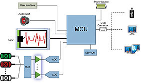
The core function of a Electrocardiogram (ECG) is to measure the voltage potentials across the body, which are created with each contraction of the heart wall. The ECG then conditions the cardiac signals and outputs them as waveforms, either onto a display screen or as a print-out. For basic ECGs this is often the limit of their functionality, however, new ECGs aim to do far more than simply output a waveform. Advanced features, such as storing waveforms, using wireless communications to transmit data, and post-signal processing, are increasingly being incorporated into the ECG feature-set. The amplifiers used within the signal-conditioning circuit are central to the implementation of these advanced features. In the ECG block diagram, shown in Figure 1, the amplifiers are shown in green in the lower, left section of diagram.
Capturing the signal
Typically, ECGs use either three, five or ten electrodes to capture the signal at different points on the body. The voltages which occur on the skin range in magnitude from 100µV up to 3mV, however, there can be a DC potential of close to 300mV at each electrode. It is crucial, therefore, that the front-end signal-detection circuit must be able to detect the very small target voltage, despite the presence of a relatively large common-mode voltage. Other factors
to consider are the presence of noise, such as 50 or 60Hz interference from overhead lights or monitors, movement of the patient, and electromagnetic interference from other equipment.
Given the extremely small magnitude of the target signal, an amplifier is required to extract the cardiac signal from the common-mode voltage and noise, and to provide gain on the signal. There are a number of factors which influence an amplifier’s ability to extract and amplify a signal, and careful consideration should be given to common-mode rejection, input offset voltage and offset voltage drift, as well as output swing and amplifier noise.
Increasing accuracy
Despite the fact that the target signal is typically less than one millivolt, the electrodes may have a DC potential in the order of several hundred millivolts. Using an instrumentation amplifier configuration, allows the amplifier to cancel any signal which is common to the differential inputs, either from the electrodes or common-mode noise such as 60Hz interference, while also amplifying the cardiac signal. To ensure that the amplifier can handle differential inputs and common-mode noise, it is important to consider the common-mode rejection of the amplifier circuitry at DC as well as across frequency, especially at line-level frequencies of 50 or 60Hz. Choosing an amplifier with a high common-mode rejection will remove more of the unwanted noise and enable measurements of higher accuracy.
Minimising output error
One of the key functions of the amplifier is to provide gain on the relatively small target voltage, increasing the resolution of the detector circuitry. Due to the high amount of gain required in ECG applications, the offset voltage of the amplifier is crucial. Any voltage offset caused by the amplifier will also be multiplied by the gain on the circuit. Assuming that the contraction of the heart creates a 1mV potential on a given electrode, and the amplifier circuitry is configured for a gain of 1000, the output of the amplifier circuitry will ideally be 1V. However, if the input offset of the amplifier is 100µV, this will create an error at the output of 100mV, or 10 per cent.
It is important, therefore, to remember that the input offset error of the amplifier is input referred, and will scale in proportion to the gain of the amplifier.
Like all electrical components, amplifier behavior changes over time and temperature. This is certainly true of the amplifier’s voltage offset which can generate a higher rate of error as the offset drifts. The voltage-offset error can be minimised by selecting a low-drift amplifier, such as an amplifier with an auto-zero based topology, or by implementing periodic system calibrations to calibrate out the offset and drift.
In the above example, a 1mV potential from the electrode produced a voltage change of 1V on the output of the amplifier circuitry. For a 5V single-supply system, this would suggest that the amplifier circuitry could accurately detect voltages from zero to 5 mV, assuming that the amplifier output could swing to both supply rails. If the amplifier does not support a rail-to-rail output swing, the overall range of voltages that could be accurately detected would be less and would therefore limit the dynamic range of the detection circuitry.
Noise error
Amplifier noise is another important factor which can affect the the accuracy of ECG measurements. An amplifier’s noise may not be constant over frequency, especially at low frequencies where 1/f noise can become the dominant source of noise. In an ECG application, the signal bandwidth of interest is typically from DC up to 100Hz, so 1/f noise will be yet another source of error.
Conclusion
ECG machines are moving beyond the simply measuring the electrical activity of the heart. Today, ECGs can perform auto?nomous signal analysis, provide real-time displays, and even enable portable devices to record cardiac electrical activity over an extended period of time. The implementation of these advanced features relies on the accuracy with which cardiac signals can be captured and conditioned and amplifier selection and design is a critical factor in the accuracy of ECG measurements.
www.microchip.com