A long battery life is important for user satisfaction with consumer devices. For battery-powered Internet of Things (IoT) endpoints, an extended battery life lowers maintenance costs and improves reliability. As the microcontroller used in these devices can be a significant power draw, designers need to select and apply the right architecture to meet the needs of these applications. In many cases, 16-bit microcontrollers turn out to be the best choice.
While 8-bit microcontrollers are getting more powerful, their performance remains inherently limited in terms of processing power and addressable memory. This eliminates 8-bit from higher performance applications. On the other hand, systems based on 32-bit cores are often overkill for the application, especially when they consume more power than necessary.
The solution lies in the middle with 16-bit microcontrollers, the sweet spot between 8-bit and 32-bit cores. They offer the low power of a simple single-supply 8-bit microcontroller while providing some of the performance and memory advantages of 32-bit cores. If an application is not intensely multi-threaded, and if the memory requirements are not too great, then a 16-bit microcontroller can provide the right level of performance with significant power savings.
Selecting a microcontroller
Selecting the proper microcontroller for an application is one of the first steps in the design process after defining project requirements. The three mainstream choices are between 8, 16, and 32-bit microcontrollers.
It’s understated how prolific 8-bit microcontrollers have become: they’re the designers’ workhorse. There is no job too small for a low-cost, low-power, 8-bit microcontroller: they have the lowest power of the mainstream microcontroller kingdom, some with standby currents below 100 nanoamps (nA).
They are also easy to use. The 8-bit microcontroller is usually accumulator based, although some more modern architectures have a register set. The programming model is simple and limited: accumulators or a small register set with a single status register, a stack pointer, and one or more index registers. Very often the stack may be in hardware and the program counter (PC) is inaccessible to firmware.
Though popular, the 8-bit architecture hits its limits when it tries to engage in networking and communications. Almost all communications stacks and networking protocols are either 16-bit or 32-bit, making it necessary to move away from an 8-bit architecture. In addition, even high-end 8-bit microcontrollers tend to be limited to 16-bit addressing without paging, restricting firmware size and complexity.
At the other extreme, 32-bit microcontrollers have become popular for applications of all performance ranges. These are register-based architectures that easily support networking and communications. They typically have 32 bits of addressing, can support floating-point math and high-end algebraic operations, and clock rates into the gigahertz (GHz) range. The 32-bit cores have a more complicated programming model that can include multiple status registers, a PC exposed to firmware, sophisticated interrupt management, and two or more layers of firmware execution privileges.
For their part, 16-bit microcontrollers are all register-based, with architectures as simple as an 8-bitter. They tend to have good low-power performance, significantly lower current draw than 32-bit architectures, and power consumption almost as low as 8-bit cores. If the application requires high-end math, some 16-bit microcontrollers boast math co-processors that have some of the same math performance as a 32-bitter at the same internal clock speed.
There are also plenty of communications stacks to support networking 16-bit microcontrollers. Ethernet, CAN, USB, and Zigbee are some examples of protocol stacks that can run just as fast on a 16-bitter as on a 32-bit microcontroller, provided the application code has enough performance available to service the stack.

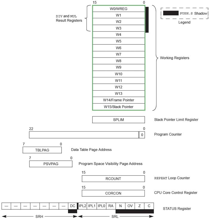
Figure 1: The Microchip PIC24F programming model is similar to a high-end 8-bit microcontroller. It has a register-based architecture with sixteen general purpose 16-bit registers, a stack pointer, PC, and five support registers. — (Image source: Microchip Technology)
Addressing large Flash memory arrays with a 16-bit microcontroller
One of the most important differences between 32-bit and 16-bit architectures is the memory addressing range. 32-bit microcontrollers have a 32-bit address bus which provides access to up to 4 gigabytes (Gbytes) of memory. Traditional 16-bit microcontrollers have had 16 bits of addressing that can only access 64 kilobytes (Kbytes). However, many modern 16-bit architectures now have up to 24 bits of extended addressing, allowing for a sizeable 16 megabytes (Mbytes) of address space.
A good example of the extended addressing approach is the low-power PIC24F microcontroller family from Microchip Technology. One of these microcontrollers is the PIC24FJ1024GA, a 32 megahertz (MHz), 16-bit microcontroller with 1 Mbyte of on-board Flash and 32 Kbytes of onboard SRAM. It uses a simple programming model similar to many 8-bit microcontrollers (Figure 1).
The PIC24 has a 23-bit program counter that can access up to 8 Mbytes of Flash program memory. It has sixteen 16-bit registers called Working Registers (WREG) referred to as W0 to W15. Registers W0 to W13 are general purpose registers (GPs) that can be used to store data under firmware control. W15 is a dedicated stack pointer (SP).
While the SP is automatically incremented and decremented by function and subroutine calls, programming exceptions, and call returns, it can also be modified by firmware just like W0 to 13.
W14 serves as the stack frame pointer (FP) with the LINK and UNLINK assembly instructions. The Stack Pointer Limit Register (SPLIM) is an independent register and is used with the SP to prevent stack overflows.
The PIC24 uses a Harvard architecture with separate address and data spaces. The Data Table Page Address (TBLPAG) register and the Program Space Visibility Page Address (PSVPAG) register are used with special instructions to access and transfer data between the address and data spaces. This is a feature common in 32-bit architectures, but rare in 8-bit cores.
The 16-bit Repeat Loop Counter (RCOUNT) register contains the loop counter for the REPEAT assembly instruction.
The 16-bit CPU Core Control (CORCON) register is used to configure internal operating modes of the PIC24 core.
Finally, the 16-bit status register contains operating status bits on the state of the PIC24 core, including status resulting from the last assembly instruction executed.

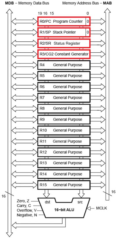
Figure 2: The MSP430 microcontroller register set is similar in configuration to other register-based 16-bit cores. The remaining configuration registers are memory mapped. — (Image source: Texas Instruments)
Microchip Technology rates the performance of the PIC24FJ1024GA606T as 16 million instructions per second (MIPS) at 32 MHz—impressive for a 16-bit core. The core has many features found in a 32-bit microcontroller, such as a 17-bit by 17-bit hardware multiplier that also supports fractional math, and a 32-bit by 16-bit hardware divider. This is useful for IoT endpoints that need to perform calculations on sensor data. The architecture can also read and write from data memory simultaneously with no performance loss. While the PIC24FJ1024GA606T has a wide range of standard peripherals, including a USB On-the-Go (OTG), it has a very low power draw for battery-powered applications. The supply voltage required is only 2.0 to 3.6 volts, and at full speed the microcontroller draws a maximum of 7.7 milliamps (mA) at 32 MHz – difficult for a 32-bit core to achieve. Firmware has fine control of the core and peripheral clocks. There are two low-power mode assembly instructions. The IDLE instruction stops the PIC24 core while allowing the peripherals to run. The SLEEP instruction stops all device operation except for the optional watchdog and external interrupt detection. Idle current is only 2.8 mA (max), and maximum sleep current is between 10 and 45 microamps (µA), depending upon the configuration of the peripherals. In its lowest power mode, sleep mode with random access memory (RAM) contents maintained, this PIC24F can draw as little as 190 nA.
For higher performance, Microchip Technology offers a high end 16-bit microcontroller as part of their dsPIC® family. An example is the 16-bit dsPIC33EP512GP 506T with 512 Kbytes of Flash and a Microchip rated performance of 70 MIPS. The dsPIC has almost the same core registers as the PIC24, with additional registers to support digital signal processing (DSP) instructions including two 40-bit accumulators and 32-bit multiply support. When upgrading a PIC24 in-system, many PIC24 microcontrollers have pin-compatible dsPIC upgrades available, providing increased performance using the same pc board.
Of course, extra performance requires extra power. This dsPIC33 requires a 3.0 to 3.6 volt supply, and when running at 70 MIPS it draws 60 mA, maximum.
Lowering power while improving performance
Texas Instruments’ MSP430FR599x microcontroller family uses the company’s ferroelectric random access memory (FRAM) program memory to achieve higher read/write performance figures at lower power than Flash microcontrollers. The MSP430FR5994IPNR 16-bit microcontroller is a member of that family with a 16 MHz clock and 256 Kbytes of FRAM.
This MSP430FR microcontroller core has performance enhancements that include a two-way associated cache with four cache lines of 64-bit line size for better FRAM performance. A 32-bit hardware multiplier enhances performance for math-intensive operations. It also has a Low Energy Accelerator (LEA) co-processor that operates independently of the main MSP430 core. The LEA can perform a 256 point complex fast Fourier transform (FFT), a finite impulse response (FIR) filter, and matrix multiplication that, according to TI, is up to 40x faster than an Arm® Cortex®-M0+.
The LEA improves performance for sensor fusion operations, enhancing images, and processing ultrasonic sensor data. These are all applications where a developer will usually first think of a 32-bit core, not an ultra-low-power 16-bit microcontroller.
The programming model for the MSP430R is very simple (Figure 2). There are sixteen 16-bit registers R0 to R15. R0 is the program counter, R1 is the stack pointer, R2 is the status register, and R3 is a constant generator (used for immediate operands). R4 to R15 are general purpose registers. The rest of the configuration registers are memory-mapped, similar to most 32-bit cores.
This performance comes without drawing more power. In standby mode with the real-time clock (RTC) running, the TI MSP430FR 5994 draws only 350 nA. In shutdown mode it draws a mere 45 nA. This is lower than any currently known 32-bit microcontroller, even lower than most 8-bit microcontrollers.

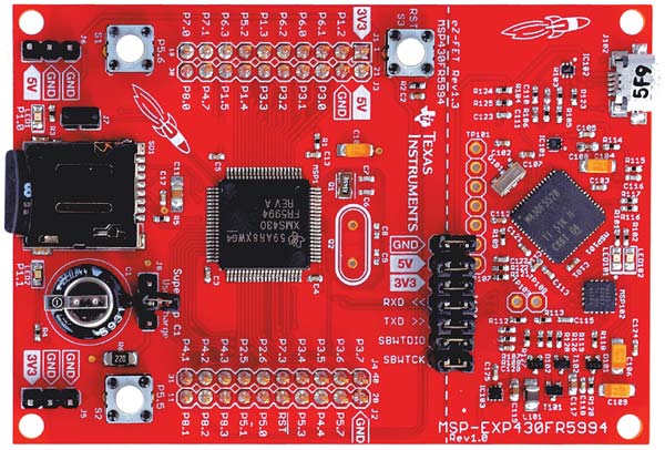
Figure 3: The TI MSP-EXP430FR5994 LaunchPad has everything a developer needs to start coding and debugging firmware for the MSP430FR5994 16-bit FRAM microcontroller. — (Image source: Texas Instruments)
The MSP430FR5994IPNR can operate from 1.8 to 3.6 volts. With firmware running out of FRAM and no cache hits, the MSP430FR requires only 3 mA. If code is running out of the cache, the current draw is only 790 µA. Combined with the LEA, this provides significant processing performance with an extremely low power draw for a 16-bit microcontroller.
Low-power applications for the MSP430FR 5994 family can be easily developed using the TI MSP-EXP430FR5994 LaunchPad™. This LaunchPad contains everything a developer needs to get started writing and debugging firmware for the MSP-EXP430FR5994 microcontroller (Figure 3).
The LaunchPad has two pushbuttons, two LEDs, and a slot for a microSD card. To demonstrate the low power capabilities of the MSP430FR5994 microcontroller, the LaunchPad has a large 0.22 Farad (F) super capacitor that is capable of powering the LaunchPad. The super capacitor is charged by plugging the LaunchPad into external power and setting jumper J8 to the “Charge” setting. It takes from two to three minutes to fully charge the super capacitor. After three minutes have passed, Jumper J8 is moved to the “Use” setting and external power is removed. Depending upon the application, the MSP430 can run for many minutes.
The LaunchPad also can be used to measure the current draw of the MSP430 and the application. The J101 isolation block has seven jumpers including a 3 volt power supply jumper, 3V3. The 3V3 two-pin jumper can be removed, and the application current can be measured through the two pins.
The LaunchPad also supports TI’s EnergyTrace™ technology and can connect to a computer using Texas Instruments’ EnergyTrace graphical user interface (GUI). This lets developers observe real-time power consumption figures from the MSP430 microcontroller and the application, allowing developers to fine tune their application for power consumption.
For example, real-time current monitoring and logging may show the MSP430 microcontroller current draw spiking at times. Current spiking can degrade the battery, reducing its life. Current spiking can be caused by misconfigured on-chip peripherals, an external inductive or capacitive load, or even firmware that tries to turn everything on at the same time.
Current monitoring and logging can show developers where to adjust the firmware to bring the spiking under control.
Conclusion
For many low power, medium performance battery-powered embedded applications, developers can choose an appropriate 16-bit microcontroller as opposed to selecting a 32-bit core. As shown, for many applications a 16-bitter can be much lower power than a 32-bit microcontroller, while still achieving the required performance.

Author: Rich Miron – Applications Engineer
Digi-Key Electronics
Rich has been in the Technical Content group since 2007 with primary responsibility for writing and editing articles, blogs and Product Training Modules. Prior to Digi-Key, he tested and qualified instrumentation and control systems for nuclear submarines. Rich holds a degree in electrical and electronics engineering from North Dakota State University in Fargo, ND.
Digi-Key Electronics | https://www.digikey.ro


