


Portable applications are constantly changing. Applications are gaining complexity with the intent to provide the end user with new experiences by adding new features. New features always provide new challenges for the power supply design. More power usually is needed although battery capacity and size limits it. Bigger displays with power-hungry backlights, more computing power, higher data storage capacities, built-in high performance cameras including flashlight function or extended wireless connectivity capabilities, are just a few examples. To keep or extend battery lifetime without increasing the size of the battery requires using low-power modes when the application blocks are not active.
By Juergen Neuhaeusler, Senior Systems Engineer – Advanced Low Power Solutions, Texas Instruments
KEY WORDS: peak-load, dynamic current limit, Lithium-Ion, Li-Ion, buck-boost converter, TPS62750, TPS63020, power management, analog, semiconductor, Texas Instruments, TI
These blocks immediately must switch to full power when needed to ensure the usability of the application is not affected. This can cause fast and big changes in the battery current. High peak currents with low duty cycles followed by almost zero current can occur. This reduces the average input current and, thus, extends battery lifetime – but it also means high and almost unpredictable peak loads at the battery.
Whether a battery configuration can handle this peak-load and how it will do it is defined by its output impedance, which differs from battery chemistries and battery connections. A possible battery switch, a protection circuit, if required, the battery connectors and the battery connection to the power management circuit together with the output impedance of the battery itself compose the source impedance of the voltage source for the application. Any high-peak current in the application will cause significant voltage drop across this output impedance and, thus, lower the real supply voltage of the power management circuit.
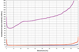
Figure 1 shows the measured output impedances of three different battery technologies. The magenta curve shows the output impedance of a dual cell alkaline in series configuration, the yellow curve shows the output impedance of a LiFePO secondary cell, and the blue curve for a Lithium-Ion (Li-Ion) secondary cell. The graph shows that both Lithium (Li)-based technologies are similar. The required protection circuit for the Li-Ion technology, which is not included in this measurement, increases the output impedance at least by the on resistance of the battery switches necessary to disconnect the cell. The alkaline cell configuration in this example suffers from the smaller cell size (AA compared to 18650) and the two cells in series configuration. The individual cell impedances are connected in series and the additional connection between the batteries is connected in series as well. In spite of this, the alkaline cells used in this test show a significant increase in output impedance during discharge compared to the almost constant value observed with the Li technologies.
When current is drawn from these batteries the voltage at the cells drops, as well as the input voltage of the connected power management circuit. It is caused by the voltage drop across all impedances of the battery and its connections. Due to the lower voltage the available power becomes lower. A connected DC/DC converter can compensate for this by increasing the input current since the demanded output power for the DC/DC converter is fixed and defined by the application circuit. At a certain battery current, increasing the battery current does not necessarily mean that the power drawn from the battery can be increased.
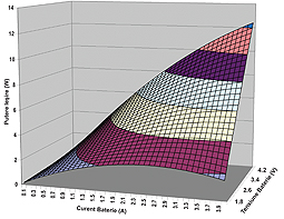
Figure 2 shows the result of a simple calculation assuming a constant source impedance of 350 mOhm, which is close to the worst case for the Li batteries shown above. The open circuit battery voltage range used for calculation is 1.8V to 4.5V. It can be seen that at higher battery voltages higher battery current still means higher battery output power. Increased power is not linear like it would be in the case of an ideal battery with 0 Ohm output impedance. But at low voltages the effect is reverse. At 1.8V, higher battery current results in less power available, if the current is higher than 2A.
If a certain power is needed, the battery cell configuration and the connections need to be analyzed in detail. It may be required to change the configuration towards multiple cells in parallel to better deal with the high currents, especially at almost discharged batteries. The voltage drop caused by peak input currents also affects the supply voltage range the power management system has to deal with. It is extended to lower voltages and requires different DC/DC converter topologies, like buck-boost converters.
Step-down converters are not able to regulate the output voltage when their supply voltage has dropped below their programmed output voltage caused by peak loads at the battery. This can result in unreliable operation of the system. Partial system shutdown triggered by undervoltage lockout detectors may occur as well as malfunctioning caused by supply voltage brownouts.
To solve these problems voltage monitoring circuits can be used to generate information for deciding to enable and disable different parts of the application, depending on available battery power. An example is not allowing the camera to flash in a mobile phone when the battery is almost discharged to ensure that mobile communication still works properly. To avoid wasting battery operation time, the available power must be predicted very accurately as well as the different use case scenarios and their worst case power demand. Higher power demand and lower power available over time due to aging effects as well as manufacturing variations must also be taken into account.
To avoid latching of the system due to overloading, the power source of the input current needs to be controlled properly. This can be done by using devices with an accurately controlled input current limit. Nice implementation examples are applications designed for working from USB power. The amount of current that can be drawn from a USB port is precisely defined. To control this properly, a power management circuit capable of working accurately at its current limit is required. The TPS62750 is an example of a step-down converter designed for this requirement.
If the power source is a battery, like the ones described above, the available power depends on the rate of discharge. If latching of the system should be avoided, the input current needs to be controlled as well. Unfortunately, since the possible maximum current depends on the battery’s rate of discharge, a constant input current limit may not satisfactorily solve the problem.
The required target value for the current limit is the lowest maximum battery current at worst case conditions. Since this occurs only at the end of discharge, this approach to a large extent significantly limits the available power at typical operating conditions.
This also limits the features that can be supported. Dynamically adjusting the input current limit according to the status of the battery allows keeping a full feature set alive at higher power available at typical operating conditions. It also helps to keep the system functional with a limited minimum feature set at extreme conditions. Getting an indication from the DC/DC converter that the currently available power is limited helps the system to decide to disable less important features in time. An example of a DC/DC converter supporting this design strategy in a simple way is the TPS 63020 buck-boost converter.
If the available input current is not sufficient to power the application, although the average current required is low enough, buffering the energy is required. This is usually done by using larger capacitors.
The peak current pulses are supported by the capacitor, which is charged up during the pauses between the pulses.
For that, smooth current limit operation of the DC/DC converter is required.
The DC/DC converter idles as soon as the output capacitor is charged to the nominal programmed voltage. The power consumption of the DC/DC converter in idle mode needs to be low, and the output impedance must be high to not discharge the output capacitor while waiting for the next load pulse.
For example, all of these features are implemented in the TPS 63020 buck-boost converter.
References
For more information about designing power supplies into portable equipment, download these datasheets: www.ti.com/tps62750-ca, and www.ti.com/tps63020-ca.
For more information about this and other power solutions from Texas Instruments, visit www.ti.com/power-ca

About the Author
Juergen Neuhaeusler is a systems engineer with the Advanced Low-Power Solutions group at TI.
Juergen is responsible for defining new power management devices, testing them and training customers to use them. Juergen received his diploma in electrical engineering from the Technical University in Munich.
Gabriela Petrache
TI – Customer Support Center
eecsc@ti.com