


Some devices use batteries while some are connected directly to the mains, but common for all is that they need a power supply. If we expand our view to look at the world, the number of powered devices is in the billions. It stands to reason that there is a huge benefit if every device tries to use and waste as little power as possible.
The demand put on power supplies with smart devices is higher than it used to be as modern applications tend to switch from spending milliwatts in stand-by mode to spending hundreds of watts when on.
To support this wide mode of operation, traditional switch mode supplies are not good enough. You need a power supply that can switch modes on the fly.
Traditionally, power supplies were implemented as an analog solution, either using discrete components or analog power devices with supporting components. This way the complete control system was implemented as an analog feedback loop. The advantage is that these systems are quite cheap and easy to design. There is a large portfolio of ASIC switch mode solutions out there, tailored for most common use cases, but many of these are not able to adapt to the changing needs of modern smart devices.
Digital power supplies on the other hands are very powerful. Fully digital power supplies digitize all input signals and subsequently all signal processing is done in the digital domain. This requires massive computing power to control, so this has traditionally been in the domain of dedicated DSPs and microcontrollers with high computational performance. Digital power supplies have many advantages over analog solutions. They can easily adapt to different topologies and easily be tweaked and tuned for maximum efficiency. The main disadvantage of a fully digital solution is cost and development complexity.
So, on one side we have analog power supplies that are cheap and fast, but not very flexible, while on the other side we have digital power that is very flexible and powerful, but also more complex and quite expensive.
Wouldn’t it be great if a third option existed, one that combined the benefits of both the analog and digital power solutions?

Figure 1: illustrates the relationship between analog, digital and hybrid power solutions.
This is where hybrid power systems come into play. In a hybrid power solution, the feedback loop is analog, but digitally enhanced. This way hybrid power systems combine digital logic with analog circuits to leverage advantages of both worlds in a single device. Having a digitally enhanced analog loop, allows us to easily change topology or control mode run time to tune the application for best possible performance.
Let’s look at a quick example to illustrate its advantages.
In battery charger applications, you need to follow strict charging characteristics for a given battery cell. Some will require charging at a fixed and regulated current in the early phase of charging, and when the battery is getting close to fully charged, it switches from current control to voltage control — where voltage is regulated, and current is reduced.
For a hybrid power solution, this is a very simple task. Just start in current mode control, and when it is time, switch over to voltage mode control. Hardware and topology remain the same, but sensing is switched.
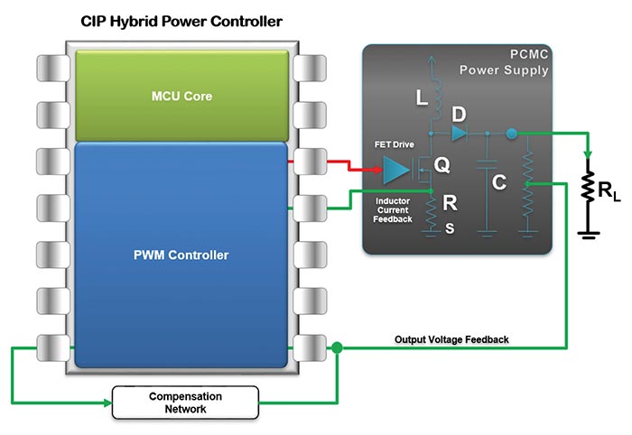
Figure 2
As mentioned, the hybrid power solution is based on a digitally enhanced analog loop system. This whole hybrid power system is set up to run in Core Independent Peripherals (CIPs). Microcontrollers with CIP hybrid power capabilities have an advanced autonomous PWM controller which is highly configurable to support a wide range of topologies and control modes.
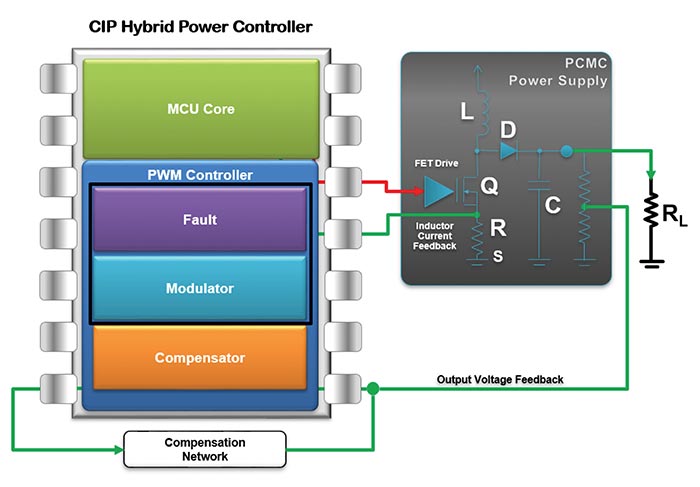
Figure 3
Figure 2 shows a very simplified illustration of a CIP hybrid power controller. It consists of a general-purpose microcontroller and a PWM controller capable of running fully independent from the rest of the microcontroller. This PWM controller is divided into three main functions, as shown in Figure 3. The modulator block is responsible for generating the switching signal to the external power transistors. Depending on control mode, it will use a current or voltage feedback signal to regulate the duty cycle. It also includes slope compensation for stability. The fault module is responsible for shutting down the power in case of short circuit or over current.
Configuring the whole system in to a single independent module is a huge advantage from a system point of view as the power supply can run independent, and the MCU can freely be used for higher level functions like communicating with a main controller, doing board control functions or providing high end control of the PWM controller.
In the case of LED lighting, getting the right color temperature requires very precise control of the current. Ambient temperature may affect this, but in a microcontroller with a hybrid power solution, the microcontroller can easily monitor ambient temperature and compensate accordingly.

Figure 4
You may say that controlling a RGBW LED strip requires four independent channels, in which case you will then be pleased to know that some of these CIP hybrid power controllers contain four fully independent PWM controllers that can all be controlled individually. They do not need to output the same voltage either. You can use one of these devices for providing 1.8V, 3.3V and 5V to your system.
Design Challenge – Keeping It Simple
Microcontrollers are generally programmed using high level programming languages like C, while power supply designers generally use analog simulation tools to design and debug their designs. Traditionally microcontroller software developers have little or no experience when it comes to designing power supplies, and likewise, power system designers often have little experience writing code for microcontrollers. This provides a challenge. How do you enable an experienced power designer to program and configure a hybrid power controller?
The answer is to provide graphical development tools that simplify the whole configuration of the PWM controller into a few simple steps. Behind the scenes, the development tool generates all necessary initialization code needed to set up the PWM controller e.g. a sync buck topology with peak current mode control with all the correct modulation, compensation and fault detect.
Microchip has released such a line of microcontrollers called the PIC16F176x and PIC16F177x. These provide up to four independent PWM controllers and are fully supported in MPLAB® X in the graphical code configurator illustrated below. This tool has been designed with analog power designers in mind and is laid out the way designers would usually go about designing an analog power supply. Instead of writing C code and configuring registers, you just select power supply topology, control mode and fill out proper values like switching frequency and max PWM duty cycle. Then the configurator takes care of the rest and generates the initialization code.
The strength here is that during normal operation, no code is running. The code is just for setting up all the interconnects in the PWM controller. Once running, the PWM controller can operate completely without MCU interaction.
More information on CIP hybrid power controllers can be found at www.Microchip.com.
Author: Arild Rodland, Product Marketing, Microchip
Social Media:
Twitter: https://twitter.com/microchiptech
Facebook: https://www.facebook.com/microchiptechnology/
Microchip Technology | https://www.microchip.com
![]()