


Medical systems utilize isolation to protect the operator, patient, the whole system or to separate noise from one part of the system to another. Where required for safety, isolation devices are governed by standards from groups such as UL and IEC; the appropriate standards are determined by the application. For example, IEC 60601 dictates safety requirements for medical devices, whereas IEC 60950 governs information technology equipment.
Within safety standards, there are certain terms related to the level or quality of isolation for medical systems:
Isolation Rating refers to the transient over voltage that the isolator can withstand. 2.5KVrms for 1 minute is a typical value, but medical systems may specify 5 KVrms for 1 minute.
Working Voltage refers to the continuous voltage applied across the isolation barrier. The isolation barrier in Working Voltage is expected to withstand this voltage over its operational life. Typical values are about 400Vrms.
Double Insulation refers to a device that has two independent systems of insulation.
Most standards today allow for a single system of isolation that has a reliability equivalent to two levels to be considered Double Insulation. These
terms are commonly used in UL safety standards.
Reinforced Isolation is similar to Double Insulation and is the term often found in IEC standards such as IEC 60601-1. Reinforced Isolation is often a requirement for medical system.
Creepage is the shortest distance along the surface of the package between two conductors on either side of the isolation barrier.
Clearance is the shortest distance through the air between two conductors. Medical applications that relate to patient safety typically require Reinforced Insulation, with a working voltage of 125Vrms or 250 KVrms, and Creepage and Clearance of at least 8mm.
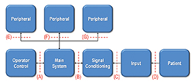
The level of isolation is determined by how the system is partitioned. Figure 1 is a block diagram for a generic medical device, with various interfaces noted to show where isolation could be implemented. The patient must be isolated from the main system, so isolation for patient safety is required at points B, C or D. In many cases, D is not an option since a sensor or other device must be connected directly to the patient; in other cases, such as in ultrasound equipment, isolation at point D is provided by the plastic casing of the sensor head. The information at point C is still in the analog domain, so it is not cost-effective to isolate here, while maintaining accuracy. Therefore, isolation in medical equipment is often implemented at point B. That leaves the operator and peripherals unprotected, so isolation may also be used at the other interfaces as well. Medical safety standards allow for two types of isolation: Means of Patient Protection (MOPP) and Means of Operator Protection (MOOP). MOPP is governed by IEC 60601, whereas MOOP may be governed by less stringent requirements, such as IEC 60950. In the example above, the system may be partitioned so that Interface B requires IEC 60601 certification, whereas Interfaces A, E, F, and G may require only IEC 60950.
Some medical systems ensure the highest level safety by complying with IEC 60601 at all interfaces. In addition, the portion of the system connected to the patient may be considered a peripheral and connected to any one of the same ports, as shown at Interfaces E, F and G. IEC 60601 also provides safety against the use of highly charged defibrillators.
Without IEC 60601 certification, anything connected to a patient must be removed during defibrillation.
ISOLATING USB
Overall, USB has some considerable advantages over RS-232:
• Expandable to 127 peripherals
• Plug-and-play operation
• Hot-swap capability
• High data rates (1.5Mbit/s, 12Mbit/s, and 480Mbit/s)
• Industry standard compatibility
• Widespread use and availability on all PCs and laptops
Despite these advantages, adoption of USB in medical systems has not been as rapid as it has been in other consumer applications. What distinguishes these segments is the need for isolation. Despite the many advantages of USB over RS-232, isolating USB interfaces is not as straightforward as isolating other interfaces.
USB is difficult to isolate because it is differential, bidirectional, and requires configuration (via pull-up and pulldown) resistors to indicate bus speed. The bidirectional nature alone presents a significant challenge since there must be some means to determine the direction of the data transmission; in an isolated USB interface, this information must be passed across the isolation barrier. Flow of control is determined by data structures rather than by control signals.
The USB interface comprises 4 lines: VDD, D+, D–, VSS.
VDD is the 5V supply, VSS is ground, and D+ and D– are the differential signals. To complicate matters, D+ and D– can also be used to send single-ended data and are used to determine the state of the bus. Pull-up and pull-down resistors at the peripheral side of the bus set the speed of the USB interface and the idle state.
By definition, data can be transmitted at one of only three rates: 1.5Mbit/s (Low Speed), 12Mbit/s (Full Speed), and 480Mbit/s (High Speed).
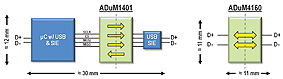
The USB 2.0 standard supports all three data rates, whereas USB 1.1 supports only Low and Full Speed data rates. It is important to note that a device can be USB 2.0 compliant without supporting 480Mbit/s. Because standard optocouplers are, by nature, unidirectional, an isolated interface using optocouplers or other unidirectional isolators must first translate the USB signals into a set of unidirectional signals, as shown in Figure 2. Here, the D+/D– lines from a microcontroller are translated into single-ended, unidirectional SPI signals. These signals are isolated and then translated back into USB signals using a USB Serial Interface Engine, or USB controller. Instead of a simple, two-wire bus, this solution adds multiple components and increases the number of wires. The result is expensive, consumes considerable board space, and requires additional design time in part because the microcontroller requires software configuration.
ADuM4160 — USB ISOLATION IN A SINGLE PACKAGE
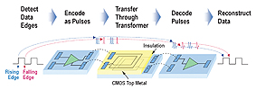
A simpler, more cost- and area-effective way to isolate USB is to use a dedicated USB isolator that can be inserted directly into the D+/D– USB signal path. The ADuM4160 provides Reinforced Isolation of up to 5KVrms with support for Low- and Full-Speed data rates. The ADuM4160 takes the functionality shown in Figure 2 and integrates it into a single package using Analog Devices’ iCoupler isolation technology. Unlike optocouplers, iCoupler isolators utilize planar transformers to transmit data across a 20μm thick polyimide insulation layer that can withstand up to 6KVrms. Data is transmitted by induction from one coil to the other. Figure 3 shows how rising and falling edges of a data stream are encoded as double or single 1ns pulses, respectively. These pulses are decoded on the receiver side to recreate the transmitted data.
iCoupler isolation has a number of benefits compared to optocouplers. The use of transformers allows data to be transmitted in either direction across the isolation barrier. Although the ADuM4160 uses dedicated transformers for transmit and receive signals, all coils are identical and contained within one package. Transformers are also inherently faster than the LED/phototransistor combination used in optocouplers. This allows iCoupler isolators to support the higher data rates and shorter propagation delays required by USB. iCoupler isolators also consume less power. The most critical advantage of iCoupler isolation, however, is the ability to integrate additional functionality. The space-saving benefits of iCoupler integration are shown in Figure 2, where the ADuM4160 consumes 75% less board space as compared to a multi- IC confi guration of USB transceivers and optocouplers.
BENEFITS OF ISOLATED USB
With a cost- and area-effective isolated USB solution that is easy to implement, medical applications may start to take advantage of the benefits of USB. In industrial systems, the lack of such an isolated USB solution forces USB to be used only for temporary connections; an operator can connect to the USB port only when the field side is disconnected. Isolated USB allows full time connection even during system operation.
In medical systems, isolated USB ports on home patient monitors can enable real-time connectivity between at-home patients and doctors to provide better, more accurate care. With isolated USB, such a home patient monitor can be connected to a personal computer, allowing real-time data transfer to a hospital via the Internet. With IEC 60601 medical grade safety approval, systems with isolated USB can even remain connected to patients during defibrillation.
www.farnell.com