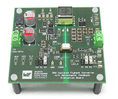
Current-controlled flyback converter with optocoupler feedback loop – Application Note ANP113 from Würth Elektronik explains what needs to be considered in design. — Image source: Würth Elektronik
Würth Elektronik has published its new Application Note “Compensating the feedback loop of a current-controlled flyback converter with optocoupler” (http://www.we-online.com/ANP113). The guide is aimed at developers looking to use a DC/DC flyback converter to achieve greater stability and reliability in power supply design. It might also be useful for those who use optocouplers for galvanic isolation of the feedback path. Applications include primary and auxiliary power supplies for home appliances, battery chargers for smartphones and tablets, as well as LED lighting. This Application Note also provides valuable assistance with power supplies for desktop and laptop computers, industrial power supplies and auxiliary supplies in motor drives, or for Power-over-Ethernet (PoE).
AppNote ANP113 explains in detail how the feedback loop can be compensated using a current-controlled flyback converter with optocoupler, and which aspects require special attention. The CTR (current transfer ratio) influences the control loop of the compensation circuit and therefore must be carefully considered in the design stage. ANP113 places particular emphasis on design constraints imposed by the optocoupler parameters and on the related solutions. The validation results of a 30-W flyback converter prototype are also included in the AppNote.


