“Zilele Educaţiei Mecatronice 2018 – România” (The days of Mechatronics Education 2018) Internal competition for mobile robots – Qualifying for ZEM 2018
With a head start in 2010, it already became a tradition that in România, once a year to be organized the competition “The Days of Mechatronics Education”, which brings together teams of students from the great university centers that have Mechatronic domain in their study program.
This year, the organizer was the University Lucian Blaga from Sibiu. At the event, the most important university centers in Romania, that are providing mechatronic training, were invited. Those universities are: University of Politehnica Bucharest, Technical University of Cluj-Napoca, University of Craiova, Technical University Gheorghe Asachi of Iasi, University of Politehnica Timisoara, University Lucian Blaga of Sibiu, University Stefan cel Mare of Suceava, University of Oradea, Transilvania University of Brasov.
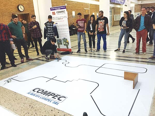
In the competition, the Mobile Robots section is raising a great interest among students. The teams compete in the contest with line follower robots built by students, according with a rules list. The task consists in running on two tracks, one of speed and one of obstacles. The speed track consists in following the line with maximum speed, and the obstacle one consists in the passage of areas where the lines are intersecting, interrupting for a certain distance, areas where a wall type obstacle appears. The contest shows the capability of students to design mechanical systems, to build electronics circuits and to develop and implement robotic control programs.
 From the desire to be close to the students, the future engineers, Aurocon COMPEC sustained the Mobile Robots team from University of POLITEHNICA Bucharest.
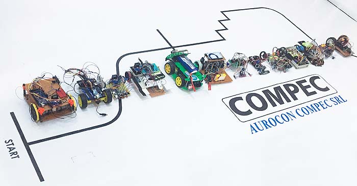
Thus, at the University of POLITEHNICA Bucharest, 12 teams of students joined the internal selection contest for the Days of Mechatronics Education. Aurocon COMPEC has provided hardware support for the developing of robotic structures (electrical motors, PCB and electronic circuits, microcontrollers, cables, connectors, 3D printing filaments, etc.). Internal competition tracks have also been made by Aurocon COMPEC.
Each team designed a mechanical structure of a mobile robot on wheels, complying with the regulations which limited the dimensions to a volume of 200mm × 200mm × 200mm.
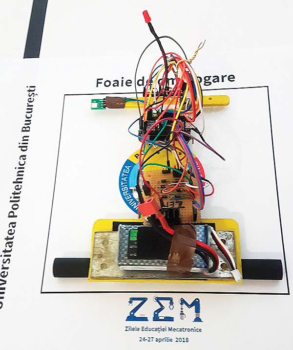
Some of the solutions consisted in 3D printed platforms, on which the motors, wheels, electronic parts and battery were placed. Other solutions started from the idea that the PCB itself can be used as the chassis, considering that the general idea was to keep the structure as compact as possible.
It may seem trivial, but a major problem was the optimal distribution of the weight on the wheels, due to which the battery positioning, as a heavy component, played a very important part. In addition to that, a structure that is too light presents the risk of wheel slipping at a certain acceleration, while a heavier one required better motors. The chosen motors were attached to the designed chassis. As for the wheels, some teams purchased some from the market, while others designed them for optimal dimension and maximum adherence. As a result, the solutions were different, all complying to the regulations.
Afterwards, the teams chose the microcontroller platform, mainly revolving around the Arduino area. Their choices were based on the number of necessary I/O for the motors, sensors etc. The regulations stated that the drivers for the motors’ command must be designed by the students, using embedded circuits, as the solutions already available on the market would not be accepted. For the circuit board, there were two options: a PCB (Printed Circuit Board) or a Perfboard on which you can place the components. The L298 circuit, which is often used in motors’ command, turned out to be very successful in this type of project.
For the line following part, certain sensors were required, such as: infrared proximity sensors for the line detection (QTR, QTI, TCRT5000), as well as a proximity sensor for the obstacle wall detection (Sharp, Ultrasonic Sensor). Depending on the loads, the batteries were chosen. Where necessary, the electronic circuit also contained voltage regulators (Eg.: LM7805).
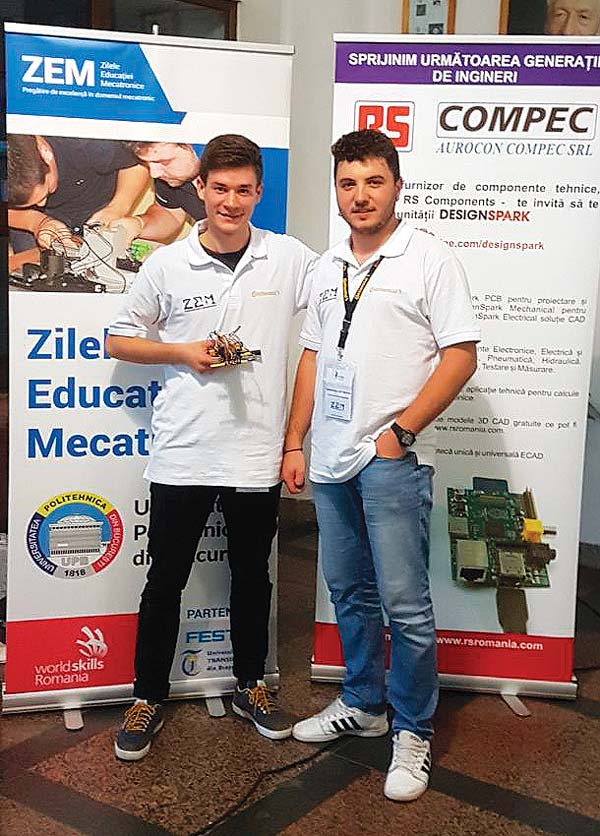
Following the local contest held at UPB, the team which qualified to the Mechatronics Education Days 2018 was composed of Emil Ionuț Niță and Andrei Silviu Colgiceanu, 4th year students in the Mechatronics department.
The national competition that came next was held at the Lucian Blaga University of Sibiu, on the 24th – 27th of April, 2018. A particularly high interest was shown towards this student competition by the students and teachers from the previously mentioned universities, as well as companies and mass media representatives attending the event.
The Politehnica University of Bucharest’s robot has done very well in the competition, placing the team in the first place.
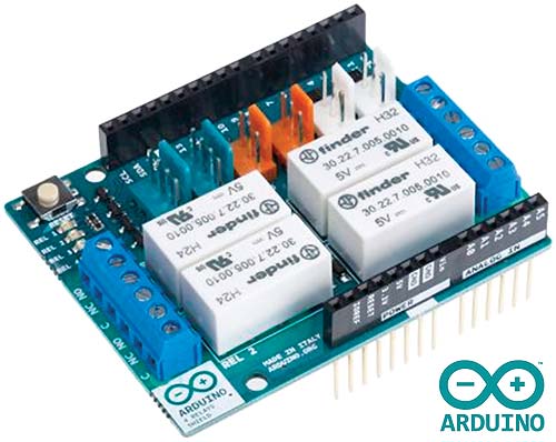 Arduino 4 relay shield
• RS Stock No.: 875-0292
• Mfr. Part No.: A000110
• Brand: Arduino
The A000110 shield features four relays that support any 3.3 V and 5 V Arduino board with the driving of high current loads. Each of the relays provides 2 pole changeover contacts (NO and NC) and have an LED for on/off status. The shield relies on the Arduino board for power. Arduino board pins control the four relays.
You can also interface various Tinkerkit modules to the shield via the shield Tinkerkit I/O and communications interfaces to add functionality to your design. For protection, the shield can be attached to a case/enclosure with four screws.
Arduino Nano 3.0 Board with ATmega 328
• RS Stock No.: 696-1667
• Mfr. Part No.: A000005
• Brand: Arduino
The Arduino Nano is a 0.73 inch × 1.7 inch (18.5 mm × 43.1 mm) board, similar to the Arduino Due.
Features & Benefits of the Nano
• On-board ATmega328 microcontroller
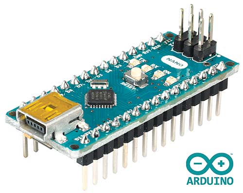 • 14 I/O pins (6 PWM)
• 8 Analog input pins
• 40 mA DC current per I/O pin
• 32 KB flash
• 2 KB SRAM
• 1 KB EEPROM
• 16 MHz clock speed
• Tx/Rx LEDs
• ICSP header
• Power LED
• Test LED 13
• Reset button
• I²C serial communications interface
• Voltage regulator
• FTDI USB chip
• Suitable for 5V power supply
Arduino M0 Pro (formerly Arduino Zero)
• RS Stock No.: 865-9004
• Mfr. Part No.: A000111
• Brand: Arduino
The Arduino M0 Pro Development Board is based on a 32-bit ARM Cortex® M0+ core and features the ATSAMD21G18MCU.
Want to be more innovative with your designs? The M0 Pro is great for IoT (Internet of Things) projects due to it’s powerful ARM Cortex® M0+ core, and introduces a number of ways to communicate with MCUs, computers, Arduino products and mobile devices.
The Arduino M0 Pro also benefits from an Embedded Debugger (EDBG) which eliminates the need for any additional hardware.
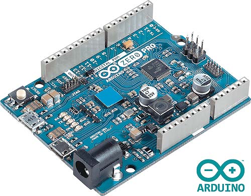 Features & Benefits of the M0 Pro
• ATSAMD21G18 MCU
• 32-bit ARM Cortex® M0+ core
• On-board Embedded Debugger
• 3.3V operating voltage
• 256 KB flash memory
• 32 KB SRAM
• Up to 16 KB EEPROM by emulation
• 48 MHz clock speed
• Power options: micro USB or external power supply
Author:
Bogdan Grămescu


