


 Many developers today are being tasked with developing low-power sensors to populate the Internet of Things. These sensors will be embedded into our streets, offices and factories and will be expected to collect data for years and share it with the cloud, most likely wirelessly. Of course, these products will also have to be low cost and require little or no maintenance, as many will be embedded in difficult to reach locations. Today, these products also have to be sustainable and ethical in terms of materials and energy use, while contributing as little as possible to climate change.
The use of batteries as a power source is one of the key areas developers have to address. It comprises many issues around limited lifetimes, product sustainability, manufacturing materials, shipment issues and the disposal of the battery at the end of its life.
However, we can look on the bright side as there is a solution that would allow us to remove or at least reduce the size of the battery. We can use the energy that’s all around us, whether in the form of light, motion, heat or some other form to power our products. This is becoming achievable for a wider range of products with the latest generation of energy harvesting power sources. These are capable of harvesting useful amounts of electrical energy from ever smaller amounts of energy in the environment, and these systems are now capable of using these small amounts of energy more effectively to power products when needed.
To allow developers to easily design products that harness energy in our surroundings as a power source, Renesas has implemented an energy harvesting controller on the RE01 family of embedded controllers. These devices are implemented on the new Silicon on Thin Buried Oxide semiconductor process, providing active current consumptions as low as 10 µA/ MHz, making them ideal for intelligent sensors powered by energy harvesting.
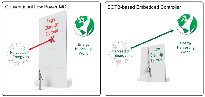
Figure 1: The start-up current problem
The biggest problem that designers have to face when designing a product using an energy harvesting power source is the start-up current of the circuitry, especially the microcontroller (MCU). When power is applied to an MCU, the power-on reset circuit will release the reset line once there is a sufficient voltage level on the supply pin. The MCU starts to initialise, so clocks start to run, registers are initialised, and any boot application runs. This can take a significant amount of current, often many mAs which most small energy harvesting sources are unable to supply. At this point, the microcontroller will fail to operate correctly as the supply collapses and the start-up will fail.
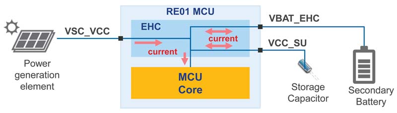
Figure 2: RE01 energy harvesting controller
In embedded designs using small harvesters, we are typically talking about small amounts of energy. For example, a 25 cm2 solar cell with a light level of 200 LUX, comparable to the light levels indoors on a rainy day in the UK, might provide 40 – 50 µA. The latest generation of thermoelectric generators with a temperature difference of 2 – 3 oC will produce a similar current level. So the EHC has to manage these small amounts of energy and store them to be used when required by the microcontroller or by other components in the system. In this article, we will focus for simplicity on the solar cell use case.
Figure 2 shows a simplified block diagram of the EHC. It illustrates the solar cell that provides the power to the device, the external storage capacitor that’s used as the original energy reservoir to support the start-up of the device, and an optional secondary battery which can be charged when enough energy is available. The EHC can optionally use energy stored in the system to power external devices, such as sensors or radios.
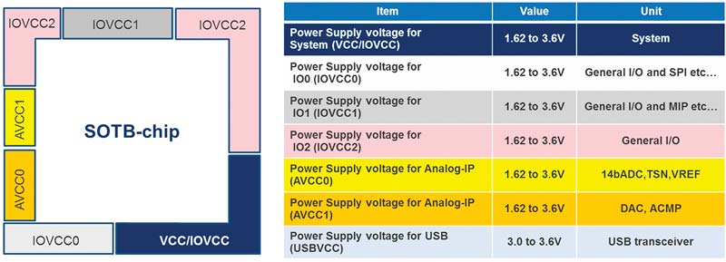
Figure 3. I/O Power domains
Before we look in detail at the EHC, we first must understand a little more about the design of the microcontroller, which has been optimised to support the minimal power available in energy harvesting applications. The RE01 microcontroller has a unique power supply design with four separately powered internal power domains and 6 external power domains. Each of these can be independently switched on or off depending on the application’s requirements. This allows the user to optimise the energy consumed by the device depending on the requirements of the application at any time. Each of the I/O peripheral and pin functions is allocated to a separate domain that can be individually powered when required. The RE01 I/O power domains are shown in Figure 3.
When the energy harvesting controller detects that voltage has been applied to the VSC_VCC pin and the supply is capable of generating at least 5 µA, then the energy harvesting cycle is started. The design of the energy harvesting controller power supply is such that the power output from the VCC pin can be supplied both to other power supply pins and to peripheral devices, such as external sensors and a radio.
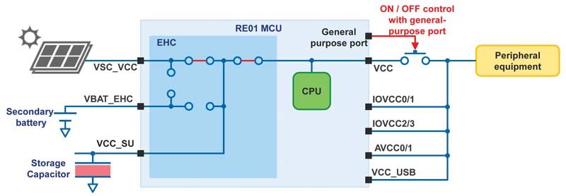
Figure 4: Energy harvesting system with simplified power supply design
When power output starts from the VCC pin, the VCC pin and the secondary battery are not connected inside the energy harvester. A simplified diagram of the power supply circuit is shown in figure 4. At this time, if the I/O domains and the external devices are connected directly to the VCC, the power they consume may be larger than the output of the solar cell and the energy held in the storage capacitor will be insufficient. In this case, the MCU will not be able to operate correctly and the start-up cycle will fail.
In order to avoid this phenomenon, a mechanism to separate these circuits from the power is necessary. Figure 4 shows a switch installed between the VCC pin and the peripheral devices, and the load switch is controlled on/off by using a general-purpose port. For this reason, one of the I/O domains is always powered. (The load switch should be turned off at start-up and turned on after the secondary battery is fully charged.)
Let’s look in more detail at how the energy harvest controller (EHC) operates. It comprises several switches and associated control logic. This circuit controls where the current flows in the device during operation.
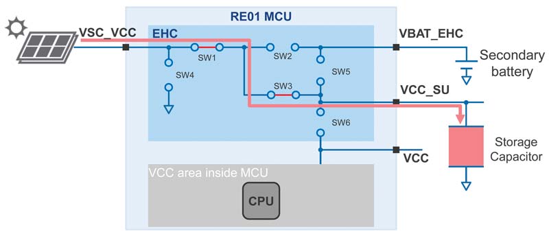
Figure 5: Power supplied by the solar cell charges the storage capacitor
First, let’s look at the initial charging period, when voltage is first applied to the device from the solar cell. In this case, shown in Figure 5, power is supplied from the solar cell to the EHC. However, rather than starting up the microcontroller, switches SW1 and SW3 are closed so the energy available is used to charge the external storage capacitor.
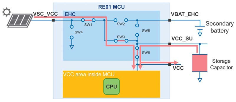
Figure 6: MCU starts up powered by the energy stored in the storage capacitor
The EHC monitors the state of the capacitor to detect whether it contains sufficient energy to power the MCU. The capacitor should be dimensioned correctly to supply enough energy for the MCU to complete its initialisation routines. Power is applied to the MCU inside the RE01 by closing switch SW6 and the reset signal is released. At this point, current is also output from the VCC pin, so care should be taken to minimise any current consumption by external circuitry powered by this pin. This process is shown in Figure 6.
Once the MCU has started and has run its initialisation software using the energy in the storage capacitor, the MCU changes state into one of its ultra-low power modes to allow the storage capacitor to be recharged. Once this is complete, we can look to charge the secondary battery (or supercap if preferred). In this case, switch SW3 is opened and switch SW2 is closed to divert the available energy to charge the battery. This is done under the control of the MCU, which monitors the state of the battery.
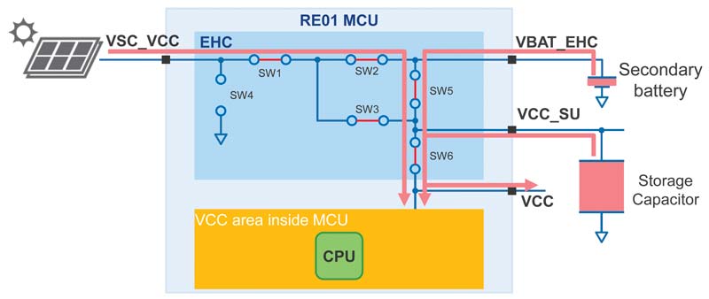
Figure 7: All energy reservoirs charged and CPU powered
The MCU monitors the state of the secondary battery (or supercap) and when it is charged we can release the full power of the device as required. With a charged battery, we can power external sensors or a radio as required, and can increase the MCU speed and peripheral function. This operating state is illustrated in Figure 7.
The energy harvesting controller is still monitoring all the voltage levels on the device, including the voltage levels on the storage capacitor and on the secondary battery. If the voltage across the capacitor drops below a set threshold, the charging process of the secondary battery is temporarily stopped to recharge the storage capacitor. When the storage capacitor is fully recharged, the secondary battery charging can start again. This cycle can be repeated as many times as required during operation.
The energy harvest control circuit also has a function to prevent the overcharging of the secondary battery. When the power supply from the solar cell is too large and the secondary battery is overcharged, the switch SW2 is turned off to protect it.
When the power generation element stops producing current, the operation continues with the power supplied from the secondary battery. This process is shown in Figure 8. There is also a reverse current prevention function to stop any damage caused by power flowing back to the solar cell: the circuit inside the EHC is disconnected.
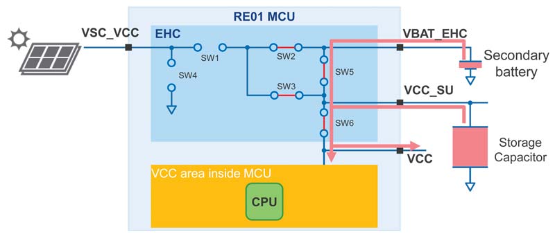
Figure 8: MCU operation continues when power fails from the solar cell
The application will continue to run, powered by the energy contained in the secondary battery and storage capacitor, until these are discharged. As the EHC monitors the voltage levels on both these devices, it will generate a warning that the power is failing to allow the system to power down gracefully before the energy supply is exhausted.
The EHC allows users to usefully manage the energy from an energy harvesting source, generating currents as low as a few µA, and store this energy to be released when required by the application.
The typical power supply cycle is shown in Figure 9, including the start-up of the EHC when power is first supplied from the solar cell. The diagram also illustrates how the MCU is released from reset. The voltage on the storage capacitor drops; the MCU then initialises, sets up the harvester and enters a low power state while still executing code slowly and consuming around 1 µA. The storage capacitor is then recharged and the secondary battery starts charging. When the secondary battery is charged and interrupt is generated, there is enough energy available to switch the MCU into full speed, and switch on external sensors and a radio as required. This can be done under the control of the MCU’s application. When the secondary battery is discharged and the voltage falls to a predetermined limit, the system gets a warning to reduce power and the cycle starts again.
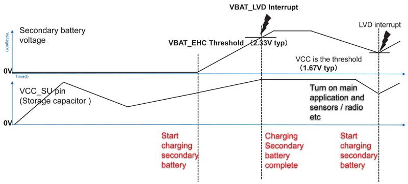
Figure 9: Waveform diagram showing power status of storage capacitor and secondary battery during operation
The energy harvesting controller implemented on the RE01 family of microcontrollers allows users to easily implement the hardware required to use many types of energy harvesting power sources. The EHC enables us to both overcome the start-up limitations of normal microcontrollers and manage the energy available to power the complete application.
The EHC allows us to look on the bright side of how to power our products in future, if we are expected to populate the Internet of Things with billions of intelligent communicating devices to sense and record the environment around us. Energy harvesting provides the ideal solution to power these devices, either to remove the need for batteries, or at least allow the local recharging of secondary batteries to remove the need for battery replacement and remote recharging. This is really the bright side of the IoT.
![]() Author: Graeme Clark, Principle Engineer, Renesas Electronics
Author: Graeme Clark, Principle Engineer, Renesas Electronics
Graeme Clark has been with Renesas Electronics Europe, and previously Hitachi Electronics, working with low power microcontrollers in a variety of roles for over 20 years. He is now responsible for the introduction of the new SOTB-based embedded controllers into the European market.
Renesas Electronics Europe | https://www.renesas.com
![]()