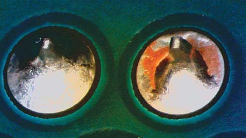
Although, the OSP finish possesses some very interesting properties, it is seen by many as a low cost solution for low cost electronics. The main reason for this is that the solderability of the OSP coating degrades quite quickly after a lead-free reflow process.
This can result in problematic through hole wetting in wave and selective soldering. This case study focusses on finding the limitations of an OSP coating in terms of through hole wetting in a selective soldering process with two different lead-free alloys. A standard SnCu based alloy and the new enhanced low melting point alloy LMPA™-Q.
The ever increasing packaging density on PCB boards and the changeover to lead-free alloys have played a major role in the evolution and choice of PCB board finishes.
The correct choice of a PCB finish usually involves the assessment of the pros and contras that are inherent to each finish and in most cases depends on the application and its requirements. These requirements can for example be: mechanical strength of the solder joint, planarity of the finish, pollution of the solder bath, storage time, degradation of the finish after reflow and last but not least cost.
Despite its limitations in planarity, the HAL finish has succeeded to maintain a fairly wide acceptance on most markets. Also NiAu has established itself as a reliable finish, although Au pollution in the solder bath or solder joint might be of concern to some. Where I-Sn appears to be more popular in Europe, I-Ag seems to have the preference in the Americas. The OSP- finish is being used quite a lot in Asia but has less acceptance in the rest of the world.
Although, the OSP finish possesses some very interesting properties, it is seen by many as a low cost solution for low cost electronics. The main reason for this is that the solderability of the OSP coating degrades quite quickly after a lead-free reflow process. This can result in problematic through hole wetting in wave and selective soldering. Beside this disadvantage however, the coating has very interesting properties. The application process of OSP in PCB manufacturing is easy and has little impact on the solder mask, it has very high planarity, good storage stability and it is cheaper than all the other finishes. This case study focusses on finding the limitations of an OSP coating in terms of through hole wetting in a selective soldering process with two different lead-free alloys. A standard SnCu based alloy and the low melting point alloy LMPA™-Q
 Test setup
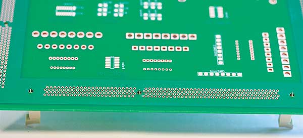
A double sided FR 4 board with an OSP coating commonly used in Asia was chosen as a test board.
• The test board has through holes for a DDR3 connector that are connected to Cu-mass planes on both sides of the board for a more realistic thermal behavior.
• The boards will be soldered in three different conditions: Fresh, two times aged with a reflow profile with peak temperature of 200°C and two times aged with a reflow profile with peak temperature of 240°C.
• The reflow profile of 200°C will simulate the ageing of the OSP coating when submitted to a double sided reflow process with an LMPA™-Q solder paste.
• The reflow profile of 240°C will simulate the ageing of the OSP coating when submitted to a double sided reflow process with a standard lead-free solder paste.
• Time between ageing in reflow and selective soldering is 48 hours. In practice, OSP degradation is sometimes already witnessed after 4 hours.
• An Sn finished DDR3 connector was chosen because of its high pin density of 240 pins with a 2 mm pitch. This will allow for enough results to assess the through hole wetting performance. A secondary difficulty for this connector is bridging but this was not the scope of this case study. A DDR3 connector is often used in computer technology for board to board connections.
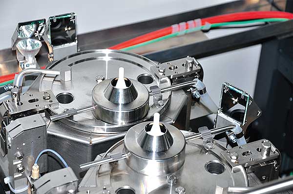
• Selective soldering tests will be performed on a Kurtz Ersa Ecoselect 1 machine with a standard SnCu based alloy and the low melting point LMPA™-Q alloy.
• A 14 mm nozzle allows to solder the connector in one stroke. The wettable nitrogen flooded nozzle provides for stable and repeatable soldering conditions.
• The water based selective soldering flux SelectIF 2040 was used for all boards.
• Lower preheating temperatures compared to wave soldering are sometimes used in selective soldering in combination with higher soldering temperatures to gain process time. A preheating temperature of 80°C measured on the top side of the PCB board will be used for all boards.
• The test will start with a soldering temperature of 285°C for both alloys.
This is a common soldering temperature for selective soldering with standard lead-free alloys. The soldering temperature will be stepwise reduced.
• For each soldering temperature the soldering speed will be stepwise increased starting from 5mm/s.
Test results and discussion
• All boards are visually inspected under a microscope and by X-Ray.
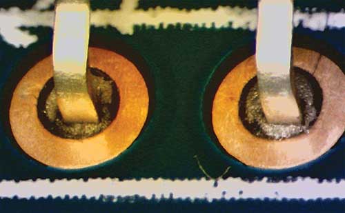
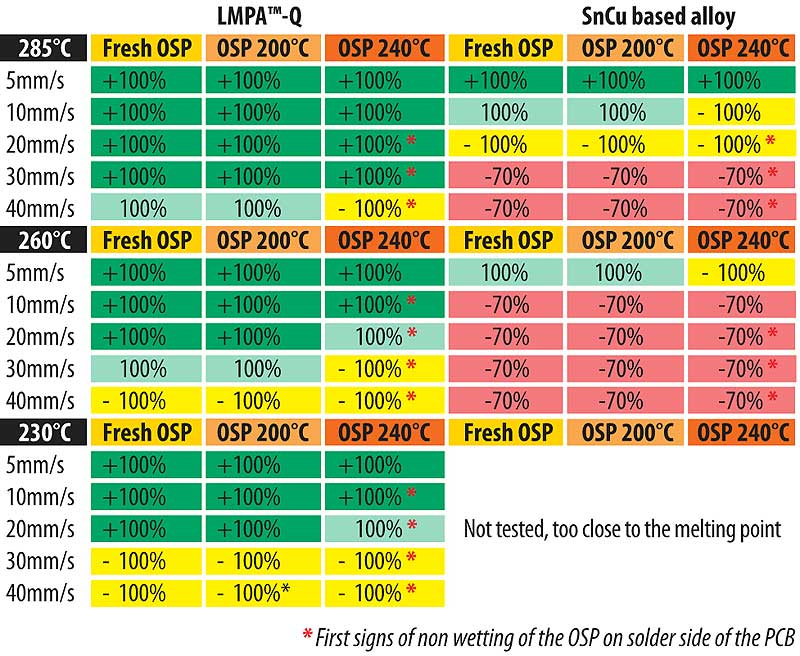
• Through hole wetting performance is divided into 4 categories:
1) + means that the barrels are filled with a filet to the top side of the through hole.
2) 100% means that barrels are filled without a filet to the top side of the through hole.
3) -100% means that the barrels are filled in between 70% and 100%
4) – 70% means that the barrels are filled less than 70%
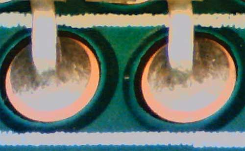
• In the table with the soldering results, signs of partial non wetting of the OSP on the solder side of the through holes are marked with a red asterisk (*).
• The results clearly show a difference between the boards aged with a standard lead-free reflow profile and the boards aged with a reflow profile for
the low melting point alloy LMPA™-Q.
• The boards aged with a peak of 240°C have consistently worse through hole filling performance than the boards aged with a peak of 200°C
• There is hardly any difference between the through hole filling performance of the fresh boards and the boards aged at a peak of 200°C.
• Furthermore, signs of non wetting of the OSP on the solder side are nearly only witnessed on the boards aged with a peak of 240°C.
• The LMPA™-Q alloy has better through hole wetting performance than a standard SnCu based alloy at similar settings. This result is anticipated because of the lower melting point of the LMPA™-Q alloy and hence bigger thermal process window.
Conclusion
The degradation of OSP after reflow is influenced by the peak temperature of the reflow profile. A standard lead-free reflow profile has drastically more impact on through hole wetting and non wetting than a low melting point reflow profile. Boards aged with an LMPA™-Q reflow profile achieved nearly the same soldering results than boards that were not aged.
Using low melting point alloys can eliminate the degradation problem of OSP and facilitate the overall use of this finish.
A secondary conclusion is that the LMPA™-Q alloy allows for lower soldering temperatures and faster soldering speeds to get good soldering results. This can substantially increase the throughput capacity of selective soldering machines.
More info? ▶▶▶ www.lmpa-q.com
Author: Steven Teliszewski, Technical Sales Manager,
Interflux® Electronics N.V.
For more information, please contact:
Eng. Ciprian Varga, Technical Director
![]() Comet Electronics | www.comet.srl.ro | office@comet.srl.ro
Comet Electronics | www.comet.srl.ro | office@comet.srl.ro
Str. Sfânta Treime Nr. 47, Bucureşti, Sector 2
Tel.: +40(0)21 243 2090 | Fax: +40(0)21 243 4090


