


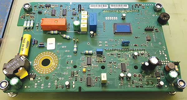
Figure 1: Megger’s electronic unit of a high accuracy hand held measuring device
Current lead-free soldering temperatures can damage temperature sensitive components. Moreover they can cause a shift in the properties of some components which can impact the functionality of sensitive electronic devices. An easy way to solve this problem is to use a soldering alloy with a lower melting point that allows for lower soldering temperatures. Currently however these alloys have limitations in shock and vibration resistance. This case study investigates the suitability of the new enhanced LMPA™-Q alloy for a handheld high accuracy measuring device from the company Megger Instruments Ltd in the UK.
It is a well-known fact that current lead-free soldering temperatures can damage temperature sensitive components and even PCB board materials. Nearly every electronic unit has some critical components on it. These can for example be: Capacitors, BGAs, LGAs, fuses, displays, crystal oscillators, LEDs, displays, components with a plastic body, coils and transformers …
Damage by thermal stress after soldering can in most cases be determined by either visual, optical, X-ray, ICT or functional testing.
It is a less-known fact that current lead-free soldering temperatures can also cause a shift in the properties of some components which can impact the functionality of sensitive electronic circuits like e.g. measuring devices. These kind of failures are often harder to determine.
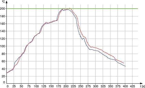
Figure 2: Reflow profile for LMPA™-Q
An easy way to solve problems related to too high soldering temperatures is to use a soldering alloy that has a lower melting point. Lower melting points allow for lower soldering temperatures. Currently however these alloys have limitations in mechanical strength. Shock and vibration resistance tend to be the weakest points. This limits the field of use of these alloys.
The LMPA™-Q low melting point alloy has been specifically developed to overcome these limitations.
This case study investigates the suitability of the LMPA™-Q alloy for a handheld high accuracy measuring device from the company Megger Instruments Ltd in the UK. This device is currently being soldered with an SnAg3Cu0,5 alloy and is sensitive to the heat in the soldering processes. Furthermore the device needs to be shock resistant in the field.
Assembly of the electronic unit
The electronic unit consists of a double sided I-Ag finished PCB board with SMD and through hole components. The temperature sensitivity mainly lies in the different capacitors on the board that are all somehow affected by heat. The boards are printed with the DP 5600 LMPA™-Q solder paste with ROL0 classification. The units are reflow soldered in a full convection oven without nitrogen and with a profile with a peak temperature below 205°C. This reflow profile will indulge the T°-sensitive components. The through hole components are being soldered with LMPA™-Q solder wire.
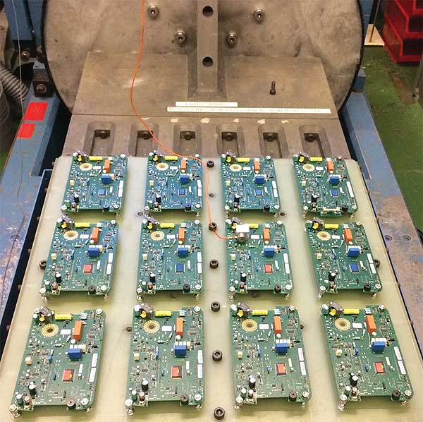
Figure 3: Vibration & shock testing
Vibration and shock resistance testing
Handheld devices need to have good shock resistance in the field. In the past this particular property has proven to be the weak point of traditional low melting point alloys. Hence, the suitability of LMPA™-Q alloy for this device will be tested accordingly.
The electronic unit is submitted to vibration and shock resistance testing according to the test standards described in BS EN 60945 and BS EN 60068. For objectivity purposes, the test are performed by a third party specialized testing lab.
The Half Sine shock test will perform shocks in both directions of all three axes. Shocks will last 11ms with a peak acceleration of 30G or defined by practical limitations of the test setup. In this case, the shock in the X-axis was limited to 10G due to breaking off of the measuring sensor with higher peak accelerations.
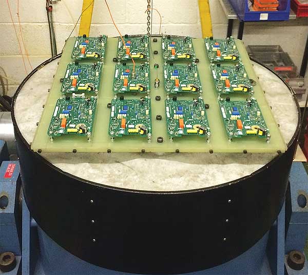
Figure 4: Vibration & shock testing
Shocks in Y and Z-Axis were at 30G. As a reference, 10G is equal to 4 times the shock a mobile phone experiences when dropping from 1 m on a concrete floor. The vibration test will start with a resonance frequency search on the electronic device in all 3 axes. The resonance frequency for a device is this frequency on which it experiences the highest forces. It is different for each single device and also for each axis.
A 2H vibration endurance test with a peak acceleration of 3G will be performed on the found resonance frequency. If no resonance frequency is found, a standardized endurance frequency of 30Hz will be used with a peak acceleration of 3G.
In this case, only for the X-axis a resonance frequency of 82.92Hz was found.
Results and extended testing
After shock and vibration resistance testing, the units soldered with the LMPA™-Q alloy were subject to visual inspection. None of the units showed signs of failures or misalignments.
At Megger Instruments Ltd, the units were subject to ICT and functional testing. All units passed.
From these results can be concluded that the LMPA™-Q alloy has sufficient mechanical strength for handheld devices.
However, to get a better idea how the LMPA™-Q holds up against the SnAg3Cu0,5 alloy, comparative vibration endurance tests were started up.
Comparative shock testing is more difficult due to the previously mentioned limitations of the test setup. Shock and vibration resistance tend to go hand in hand as vibration actually is a fast sequence of shocks.
The same handheld high accuracy measuring device was chosen for this test. Electronic units soldered with SnAg3Cu0,5 and LMPA™-Q were provided to the test lab

Table 1: SAC fails first in comparative vibration testing
As vibration in the X-axis is expected to be more critical, it was chosen as the only axis for this comparative test.
A standard test frequency of 30Hz in combination with a peak acceleration of 18G was used as an initial setting for a 30min vibration endurance. After visual inspection, the acceleration or frequency was stepwise increased, until a first failure was noticed.
The first failure manifested itself on an electronic unit soldered with the SnAg3Cu0,5 alloy at a frequency of 50Hz and a peak acceleration of 25G.
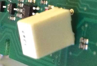
Figure 5: SAC solder joint failure
Results and conclusion
As the LMPA™-Q alloy passes the required shock and vibration tests and the SnAg3Cu0,5 alloy fails first in comparative vibration testing, the LMPA™-Q alloy is suitable for the production of Megger’s handheld high accuracy measuring device.
The LMPA™-Q alloy allows for lower soldering temperatures in the soldering processes and temperature sensitive components are less affected by heat. This results in a more reliable production process and higher quality of the electronic device.
Based upon the good results, Megger Instruments Ltd has started the procedure to homologate the LMPA™-Q alloy for more processes and products.
More info? ▶▶▶ www.lmpa-q.com

Author: Steven Teliszewski, Technical Sales Manager,
Interflux® Electronics N.V.
For more information, please contact:

Eng. Ciprian Varga, Technical Director
![]() Comet Electronics | www.comet.srl.ro | office@comet.srl.ro
Comet Electronics | www.comet.srl.ro | office@comet.srl.ro
Str. Sfânta Treime Nr. 47, Bucureşti, Sector 2
Tel.: +40(0)21 243 2090 | Fax: +40(0)21 243 4090