


Using Digital Signal Controllers (DSCs) for sensorless control of Brushless DC (BLDC) motor control to bring this technology within reach of low-cost, mass applications, explains Charlie Ice, of Microchip Technology Inc.
by Charlie Ice, Microchip Technology Inc.
As the technology of choice for many high- to mid-range systems, Brushless DC (BLDC) motors offer a constant or variable speed drive combined with high reliability and ease of control. The use of even a few Hall Effect sensors, however, adds to the total system cost which can take BLDC out of the reach of low-cost applications. Previous attempts at sensorless control have also been priced out of the reach of mass-market applications by requiring expensive controllers to run the algorithms used to replace the sensors.
Now, however, with volume costs of close to one dollar per unit, Digital Signal Controllers (DSCs) such as such as Microchip’s dsPIC33FJ15MC102, can overcome these challenges and make sensorless BLDC motor control a viable choice for low-cost applications.
Sensored BLDC
To understand how sensorless BLDC motor control works, it is useful to consider the basic sensored control model.
The BLDC motor uses an energised coil, or stator, which causes a permanent magnet on the rotor, or shaft, to align with the coil, and rotate the rotor to generate torque. In a three-phase BLDC motor the stator’s three coils, or phases, are turned on and off sequentially in advance of the rotor. To make the rotor spin smoothly, the motor is built using multiple sets of coils for each coil or phase and each phase must be turned on and off in a specific order to make the rotor rotate. The position of the rotor dictates which phase needs to be turned on or off. Therefore, it is critical that the position of the rotor is known, and that the controller actively switches the phases on and off so that the BLDC motor can operate. The simplest way to calculate the rotor’s position is to use Hall Effect sensors, which generate pulses which allow the controller to identify the rotor’s position. With the rotor’s position identified, the basic BLDC controller just needs to lookup which pattern for the three phases corresponds to the position of the rotor, and switch the phases to that pattern.
Sensorless BLDC
Taking a closer look at the three phases of a BLDC motor can help to explain how a sensorless BLDC algorithm can calculate the position of the rotor.
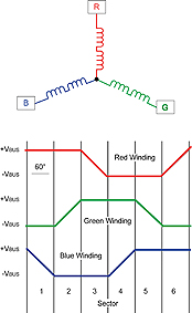
In trapezoidal control, one phase is pulled high (+VBUS), one phase is pulled low (-VBUS), and the third phase is inactive, at any one time. The waveform of each phase is shaped like a trapezoid, as shown in Figure 1. When the rotor passes by a phase, the permanent magnet on the rotor induces a current in that phase that results in a voltage known as back Electromotive Force (EMF). The back EMF is dependent on the number of turns in each phase winding, the angular velocity of the rotor, and the strength of the rotor’s permanent magnet. The back-EMF waveform of each phase is related to the position of the rotor, so the back EMF can be used to determine the rotor’s position.
Although there are many methods of using back EMF to determine the position of the rotor, one of the most common and robust is zero-crossing detection.
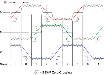
When one of the back-EMF signals crosses zero, the controller must switch the pattern on the phases. This process, known as commutation, is shown in Figure 2. In order to keep the rotor advancing, there must be a phase shift between the point at which the zero crossing occurs and when commutation occurs. The controller must calculate and compensate for this.
A simple way to implement zero crossing is to assume that a zero-crossing event occurs whenever the back EMF on any of the phases reaches VBUS/2.
This method can be easily implemented by using a few operational amplifiers, configured as comparators. However, this does present a number of problems: The back EMF is typically less than VBUS, so the zero-crossing events do not necessarily happen
at VBUS/2; In addition, the properties of each phase may be different, so the back-EMF voltage for a zero crossing on one phase could be different from that of the other phase. Finally, this simplistic sensing method causes positive and negative phase shifts in the sensed back-EMF signals.
Real-world BLDC
In real-world applications, the zero-crossing threshold voltage varies considerably. This variable threshold voltage is, however, equal to the voltage of the neutral point of the motor, as the neutral point of motor is the average of the back EMF of all three phases. Therefore, whenever the back EMF of any phase equals the motor’s neutral point, a zero-crossing event has occurred and the controller needs to commutate. This can be done by using resistors and operational amplifiers, or by using the ADC module and software on the controller. With a programmable controller, such as a dsPIC® DSC, the back EMF for each phase can be sampled using the ADC module, and the neutral point can be easily recreated in software by taking the average of the three back-EMF signals. The software can then compare this value to the sensed back EMF of the three phases and detect when a zero-crossing event has occurred. Once a zero-crossing event has occurred, the controller commutates the motor and the process starts again. Using the back EMF of the motor to detect zero crossings means that the sensor can be eliminated from the system without compromising performance.
Real-world systems also introduce other challenges to sensorless operation. First, at low speeds, the back EMF is very small and very difficult to detect. So, the controller must guess the rotor’s position until the motor begins to spin fast enough to generate enough back EMF to operate in sensorless mode. A software-programmable controller enables the system startup to be tailored to each application, which can minimise the effects of this issue. Another challenge is switching noise from the MOSFETs. As the MOSFETs switch to change the voltage on each phase, they introduce noise into the back EMF which is sensed by the controller’s ADC module. This noise needs to be filtered out, in order to accurately recreate the back EMF of each phase. A DSC has a DSP engine built into the processor, which can easily handle the computations needed to implement a digital filter and eliminate this switching noise. The use of a software-programmable controller can also provide easier solutions to other challenges, which are specific to each application.
Reducing development cost
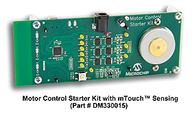
New development tools, optimised for sensorless BLDC control, can significantly cut the cost and development time for implementing sensorless BLDC in mass-market and other applications. Microchip’s motor-control starter kit, shown in Figure 3, costs less than $100 and includes detailed application notes, as well as example software and hardware schematics.
Motor-controller suppliers, including Microchip, also typically provide downloads of software and hardware files free of charge, which makes the learning process even easier.
Conclusion
DSCs are taking the cost out of BLDC motor control. Sensorless BLDC motor control can be implemented using DSCs which have a volume cost which is close to one dollar per unit, and with development tools that cost less than $100, in addition to free software and schematic downloads and application notes. These are all good reasons why sensorless BLDC is beginning to take its place in low-cost, mass-market applications.
Note: The Microchip name and logo, and dsPIC are registered trademarks of Microchip Technology Inc. in the U.S.A., and other countries. All other trademarks mentioned herein are property of their respective companies.
www.microchip.com