


It is often necessary to have several microcontrollers performing different operations integrated in one system in order to make them function as a whole. Here we show how to connect three microcontrollers to a CAN and how to use filters in CAN nodes for the purpose of filtering messages.
By Zoran Ristic, MikroElektronika – Software Department
Whenever several peripheral units share the same data bus, it is necessary to define how the bus is accessed.
The CAN protocol accurately describes all the details on connecting several devices to a network and as such it is widely used in the industry. The protocol primarily defines the precedence of bus implementation and solves the problem of ‘collision’ within the hardware in the event that several peripheral units start to communicate at the same time.
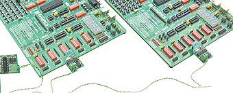
Hardware
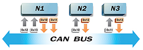
In this example, a CAN bus will be configured so that the first device sends messages consisting of 0x10 and 0x11 as their ID, while the second and third device send messages consisting of IDs 0x12 and 0x13, respectively. We will also configure the CAN nodes so that the second node responds to incoming messages containing ID 0x10 only, while the third one responds only to those containing the 0x11 ID. Accordingly, the first device is configured to receive messages containing a 0x12 and 0x13 ID (Figure 2). Message filtering is easily implemented by calling the CANSPISetFilter routine which will also handle all the necessary settings of the microcontroller registers and CAN SPI board.
In general, the CAN protocol doesn’t require a Master device to be present on the bus. However, to make this example easy to understand while still keeping it general-purpose, we will set the first device only, to initiate communication on the network and another two devices to respond to individual calls.
Software
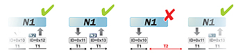
When sending a message, the Master node leaves enough time for the called node to respond. In the event that a remote node doesn’t respond within the time required, the Master reports an error in the current message and proceeds with calling other nodes (Figure 3). In the event that a peripheral CAN node responds at the same time as another node, a ‘collision’ will occur on the CAN bus. However, the device address priority and CAN alone prescribe that in this case the node transmitting the lower priority message withdraws from the bus, thus enabling the node transmitting the higher priority message to proceed with transmission immediately.
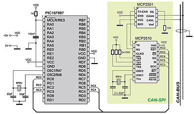
As mentioned before, we will use an internal SPI module of the microcontroller to transfer data onto the CAN bus. Some of the advantages of using the microcontroller’s internal SPI module are: the possibility of generating an interrupt when sending and receiving data;
the SPI module operates independently of other peripherals and has a simple configuration.
The CAN SPI library enables you to set the operating mode of the CAN and node filters, read data from the CAN SPI board buffer, etc.
This example also includes LEDs on the microcontroller pins indicating that the network operates properly. When node 2 responds to node 1’s call, the PORTB LEDs will be automatically turned on. If node 3 responds to the call, the PORTD LEDs will be turned on. The source code for all three nodes in the network is provided with this example. In order to create a HEX file for each of these nodes individually, it is necessary to write only one DEFINE directive in the example header.
In summary, here we have described one way of connecting microcontrollers to the CAN bus. We have also described how to detect errors by means of a communication protocol in the event that a remote node doesn’t respond as expected, how to filter messages using CAN filters, as well as how to perform communication in general on the CAN bus.
The program for this example written for PIC® microcontrollers in C, Basic and Pascal as well as the programs written for dsPIC® and AVR® microcontrollers may be found on our web site: www.mikroe.com/en/article/