


Embedded-system designers may aspire to a single-chip solution to their problem, but rarely get very close to achieving it. Their chosen microcontroller may lack an essential interface or they may need to add custom logic to augment the functions they code on to the MCU. And, interfaces to the real-world signals their design gathers from its sensors, and its outputs to drives or actuators, will demand analogue circuitry for signal-conditioning and power control.

By Mike Brogley, IP and solutions manager, Actel
Into this space, Actel has now introduced SmartFusion – a single-chip device that integrates an ARM Cortex-M3 microcontroller core, high-performance FPGA fabric developed from the company’s pASIC3 programmable logic technology, and configurable analogue functions that use a high-voltage, high-speed technology. The Cortex-M3 core is a 100MHz (125DMIPS) device with up to 512KB of flash memory and 128KB of SRAM. It is a “hard” core – that it, it is diffused in the silicon in the most area-efficient implementation. It is powerful enough to run complex algorithms, readily running precision motor control, or

even multi-axial control of several motors, and comes with a peripheral set that includes 10/100 Ethernet MAC (media access controller) and other interfaces including SPI, I2C, UARTs and RS485. Ample digital I/Os operate at up to 350MHz, support I/O levels for interface standards such as LVDS, PCI and PCI-Express, and will drive up to 24mA. Mixed-signal I/O lines run at up to 180MHz and drive up to 6mA. FPGA resources comprise up to 500k gates and 108KB of SRAM, in a flash-based fabric that supports up to 350MHz clock speeds. The flash technology yields programmable devices that are live at power-up, and secure; eliminating off-chip configuration memory removes a vulnerability to design copying. Designers can add further IP (intellectual property) protection by permanently disabling access to configuration memory after programming.
The silicon technology that builds on-chip flash, which requires elevated programming voltages, also enables high-voltage and high-performance analogue functions. SmartFusion chips will host up to three 12-bit successive-
approximation (SAR) analogue-digital converters (ADCs) that will run at up to 500 ksamples/sec at full resolution. Each ADC has a corresponding first-order, 1-bit sigma-delta DAC, with 5sec refresh and 12-bit resolution. Analogue functions are grouped within Signal Conditioning Blocks (SCBs) comprising, for example, accurate high-voltage and current monitors, temperature monitors and high-speed (50nsec) comparators. In the SCBs there are also bipolar scaling functions to condition captured signals. Labelled ABPSs, active bipolar pre-scalers, they have 1MHz input bandwidth with 1MW input impedance. Closely associated with the analogue SCBs is the Analogue Compute Engine or ACE, a completely new, semi-autonomous block that carries out extensive analogue pre- and post-processing, including sampling and sequencing of signal acquisition, without the intervention of the ARM processor.
1-chip motion control
Improving the performance of motor control has become a major priority for many design teams in industrial electronics, and the characteristics of SmartFusion chips will be an excellent match to their needs. There are many and varied motivations for better motor control, not least the drive for energy efficiency. There is a growing realisation that more sophisticated motor control schemes can yield greatly improved performance, as well as efficiency, and do so with smaller and lighter hardware.
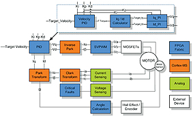
For many less demanding applications, simple control regimes will continue to suffice; but design teams dealing with more sophisticated products are being challenged to apply advanced algorithms – often, to BLDC (brushless DC, otherwise known as PMSM, permanent magnet synchronous) motors – to a very high degree of precision. Their systems must synthesise power waveforms, as the ultimate output of multi-level closed-loop systems that take in high-bandwidth, sensor-derived or sensor-less, feedback data.
Frequently, such designs are multi-axis: they demand simultaneous control of several motors to drive a mechanical system in a defined way in 3D space (a robotic arm, for example). With SmartFusion, achieving this degree of real-time control in a truly one-chip design is a realistic objective.
Time-domain optimisation
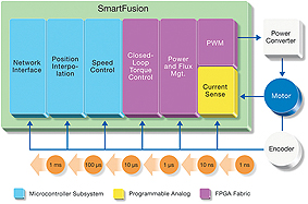
Figure A is a representation of the major functions within a precision motor control system. In this diagram, the time scale on which it must operate and respond, classifies each function. The system accepts some form of command or setpoint, and
generates power outputs to the motor to drive the system to its commanded speed or position, subject to the performance characteristics that are desirable in any closed-loop control scheme. That is, it must converge on the setpoint in the minimum time and settle to it with no overshoot, and continue to track all subsequent command inputs. At the highest level in this diagram, the control system receives commands and reports its performance. This might be via a network interface, or simply reading control settings and driving a display. At this level, a response time measured in milliseconds is adequate. Reading from left to right in Figure A, the inner control loops are shown in terms of shorter and shorter intervals within which they must react.
For example, the time scale appropriate to the speed control loop is of the order of hundreds of microseconds, or an update rate of a few kHz. A microcontroller core running at, say, 100MHz, can carry out the calculations needed for several such loops, and also run higher-level functions such as bus interfaces. Further to the right in Figure A are some of the more time-critical algorithms that are the basis for high-performance control schemes; closed-loop control of torque, and calculations of magnetic flux within the motor. These involve quantities that either cannot be measured directly (or in the case of torque, are rarely directly measured), so their values must also be computed from sensor readings or voltage measurements. To accommodate this scale of calculation – and faster, still, to execute PWM waveform synthesis on a micro-second-timescale – is challenging; which is why designers have typically turned to high-performance DSPs, or to hardware in the form of logic implemented in an FPGA. When executed in a software-programmed environment, this is the domain of hard-real-time coding, with the inner-control-loops having top-level priority over all other tasks. An FPGA fabric of gates that supports clock rates of several hundred MHz is, however, a natural environment for hardware acceleration of advanced control algorithms. At the “real-world” end of Figure A is the true-real-time domain of analogue signals: sensor inputs, and output waveforms to the power switches that drive the motor windings.
With resources of each type – MCU, FPGA and analogue – available on the same single chip, a time-domain-optimised solution becomes available; each function within the complete motor controller can reside in the environment that best suits it. The ARM processsor core can interface, report and carry out system supervision; time-critical logic functions can be coded, via standard RTL-design practices, into the FPGA fabric; and signal conditioning of real-time sensor data can take place in wideband analogue circuitry, to undergo A/D conversion at the most appropriate time. The temptation – or the budgetary pressure – to force parts of the design to handle functions for which they are not best-suited, disappears.
Inter-discipline interfacing
A single-chip device offers obvious, and significant, saving in bill-of-materials cost over a conventional motor-control or system-supervisor design. Today’s motor-control PCB might carry, for example, a microcontroller (or a DSP), and a stand-alone FPGA; plus a considerable array of analogue ICs and accompanying passive components. But there is a more subtle advantage in this strategy, that goes beyond reducing cost and PCB area. Each technology discipline has its own specialists – software code writers, RTL designers, and linear circuit gurus. When each portion of the hardware is a separate entity, the interfaces between them can be poorly-defined and the subject of negotiation on a project-by-project (or even day-to-day) basis. When the design is hosted on a SmartFusion chip, each specialist can work within a single overall design environment in which the design tools have full awareness of all of the features
of the silicon. Interconnecting analogue components with processor I/Os, or FPGA fabric with the MCU’s buses, becomes little more than a drag-and-drop operation, reducing design iterations and speeding time-to-market; subject specialists are freed to collaborate in a far more productive way.
www.actel.com