


 More important to connector design is an understanding of the different construction techniques that have been proven in harsh environments. This is something that comes through decades of experience and work in highly demanding applications. That is why, when it comes to rugged connectors, it is worth looking at the long heritage of military connectors for non-military applications.
The major advantage of opting for military standard connectors is that the designs have been refined and battle-tested over time, so have the requirements. The evolution of military standards and the connectors that follow them, closely match the demanding requirements of ruggedised systems and provide a number of options to support different needs. If a connector application does not need the full complement of ruggedisation, other options are available and may come with a lower cost. The key is to match the requirements of the application to the connector type. This does not need to be as challenging as it first appears as there are specialists who can help, with specific technical skills and many years of experience in this demanding industry.
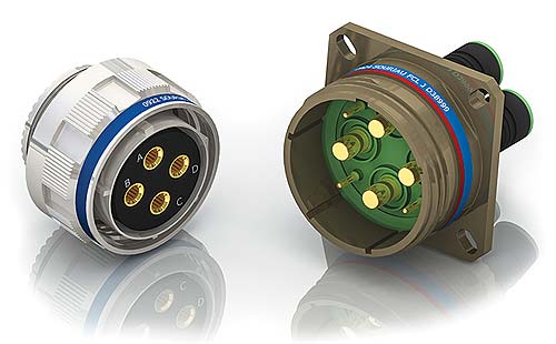
Developed more than 70 years ago, the core design of the AS50515 connector has clearly stood the test of time. The structure satisfied the requirements of a connector that offers easy engagement and disengagement, the ability to house a wide variety of contact types and excellent mechanical and electrical performance under harsh conditions.
In contrast to the connectors used on office computers and similar products, military designers opted for a circular architecture that has become a staple of rugged connectors ever since. The shape is important. Whether the interface is Ethernet, USB, parallel bus or a custom mix of signal pins, the same circular shape is a consistent feature of military-grade rugged connections because of its high performance.
The circular shape provides the basis for higher mechanical strength, particularly if the connector is subject to shocks or high forces perpendicular to the signal flow. There are no sharp angles or corners often found in commercial-grade connectors that focus such stress into small portions of the connector body.
 The AS50515 standard has limitations. These issues led to the development of a number of variants that optimise contact size for high-density interconnection, as well as providing support for features such as multi-key polarisation. Even so, the connector still has applications in sectors such as powertrain interconnection in mass transportation, and industrial robotics where high power-handling capability is essential.
The MIL-DTL-28840 standard took the circular connector concept into shipboard systems, using corrosion-resistant materials and seals to protect against sea water and other hazards. The MIL-DTL-38999 standard provided a high-density connector for increasingly complex electronic systems, following the trend towards subminiature connectors in the commercial IT space.
The longevity of the core connector design has resulted in a design that maximises usability and robustness in real-world use. Damage caused by misaligned connectors needs to be minimised. A system cannot be rendered unusable in active service conditions. Connections may have to be made by soldiers under fire – the connector design needs to be implemented in such as way that mis-mating and the resulting damage does not occur.
In a connector based on the core AS50515 design, the metal connector shell has a number of keyways that correspond with those in the connector to which it has to mate. The configuration of these keyways depends on what is best for the application.
Military connectors employ keyways, not only to ensure the two halves are aligned correctly as they are brought together, but also to prevent damage to fragile pins in high-density designs. Usually there is a master keyway providing primary location between shells. On this is superimposed a set of minor keyways to allow the orientation of the respective inserts to be altered relative to the master key. This is achieved by slightly altering the angle of the inserts in the shells. For instance, the pin insert may be placed some degrees clockwise relative to the master, while sockets are moved anticlockwise in the same manner. Thus, different pin arrangements are catered for without compromising the protection against mismating.
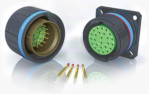
 Although the use of keyways prevents most of the potential for damage when mating connectors, there is still the danger of socket hardware injuring the pins of a high density plug with which it is to be mated. This occurs at the moment of insertion or withdrawal. The pin insert is surrounded by a cylindrical metal shield which projects well beyond the delicate pin inserts. On bringing the two halves of the connector together, this shield engages and aligns them before the pins are mated. This scoop-free design prevents damage by attempts to engage the connectors when the halves are not in line.
Once the connectors are mated, they a locked together by a coupling. A common choice is between threaded, bayonet and breech-look designs. In all cases, the aim is to add extra compression to the joint before positive locking occurs, to ensure excellent contact between the two halves of the connector. The MIL-DTL-38999 connector and similar designs have evolved to employ a triple-start threading mechanism for the dual benefits of high protection against vibration, and faster mating and unmating without a loss in connection integrity.
The choices of material and design for connector contacts have proven instrumental in the long-term stability of the military connector standards, making them highly suitable for any application that requires ruggedness. Connectors are precision mechanical devices whose interfaces are critical and subject to mechanical wear, more so than most other electrical components. If not catered for, the effects of oxidation and sulphide formation will reduce the connector’s capability. Connectors may be required to have contacts made and broken repeatedly and in conditions that encourage corrosion as well as mechanical wear. Industrial applications, as well as military, often subject the connector assembly to vibration or repeated physical force, which contributes to fatigue or abrasion of the contact materials.
These life stresses cause degradation of electrical conductivity, and can – in inferior designs – result in open, intermittent contact or excessive resistance. In some installations, mechanical strain can also adversely affect the integrity of the securing apparatus. Among the materials found in lower-cost connectors are metal alloys suitable for casting, such as zinc-based metals. The contact choices for military circular connectors focus on metals and alloys with higher endurance.
 Beryllium copper is a common focus for the leading manufacturers of circular connectors. Copper has the key advantage of being an excellent conductor but is a relatively soft metal. Alloying copper with beryllium, however, dramatically changes the physical performance. The alloy of beryllium with copper has the further benefit of being comparatively lightweight.
Small changes in the beryllium content, typically between 0.15 and 2 by weight percentage, produces alloys with widely differing physical properties. All retain an elastic modulus of around 20 million psi, around 10 to 20 per cent higher than other copy alloys. Long-term experience with the real-world performance of connectors in demanding military applications has provided the leading manufacturers with solid experience in which alloys provide the greatest overall benefit. Gold-plated contacts provide excellent conductivity for solder or crimp termination.
For the shell around the connector body, there are a number of material choices. One is aluminium that is plated or anodised for corrosion protection. A variety of plating materials can be used. Traditionally, cadmium proved to be a high-quality choice for corrosion resistance but the introduction of environmental restrictions, such as the RoHS and REACH directives mean less toxic materials need to be used in most applications. Experience has shown that zinc alloyed with nickel provides high salt-spray resistance comparable to that of cadmium plating. This performance is achieved without compromising electrical continuity.
Higher continuity, though with less resistance to salt spray is available using nickel over aluminium.
Stainless steel provides another option for the shell construction. As well as excellent corrosion resistance it is generally one of the best choices for situations that call for the ability to operate in sterile conditions – suiting the material to food and medical applications. Plating for stainless steel is generally with nickel or a passivation layer.
The internal contacts will generally need to be protected from moisture ingress, possibly to the level of a hermetic seal. Examination of the internal structure of the typical circular connectors reveals how well-suited to this the design is. There are often a number of layers of insulating material packing the space between the connector body and the contacts.
Looking into the front of the male connector, a user will see the interfacial seal. But behind that will be an insulator layer, a retention disc and finally a grommet that extends to the rear of the connector body. The female connector provides a deep insulating layer on top of another retention disc and the grommet. As well as participating in the sealing ability of the connector, the retention discs help assure a firm contact between the electrically important mating parts.
 The insulating materials are carefully chosen. Dielectric materials in low-cost commercial connectors may include polyethylene and polystyrene, possibly glass-filled for high voltage breakdown performance. Circular connector manufacturers will often specify FEP fluorocarbon or polytetrafluoroethylene (PTFE). For connectors with a sealed interface, the gasket material is typically silicone rubber.
A careful choice of insulating materials as well as contacts assures high performance in electrically demanding applications, such as high-frequency signal interfaces. These connectors will provide consistent electrical performance and mechanical reliability. Also, basing connector choice around a known and well-supported standard such as MIL 38999, assures uniform performance among products from different vendors. For example, such a standard will demand gold plating levels to a specified minimum level to guarantee conductivity.
A further advantage of the materials specified for military use lies in the typical operational temperature range of the connectors. They can be used across a wide range of temperatures, often down to as low as -65°C and up to +200°C depending on the model.
For operation in hazardous, fire-prone environments, another option is for fibre-optic connections. Because of the high signal integrity achievable using photonic transmissions, there are many options for fibre-optic connectors in military product ranges – as well as pertinent standards, such as MIL-PRF-29504 termination.
Designed to fit MIL-DTL-28840, MIL-DTL-38999 and similar connectors, the MIL-PRF-29504 standard determines performance criteria for fibre-optic termination to ensure clean mating. Because of the need to preserve optical continuity under shock and vibration, fibre-optic standards are more stringent in this respect and ensure that reliable performance is maintained in compliant products.
A combination of experience and clear standardisation that maximises interoperability and resilience makes the military circular a smart choice for a wide range of industrial applications that need to go into harsh environment applications with stringent performance requirements.
Heilind | www.heilind.de